Hi diyAudio community,
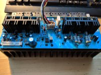
I stupidly split beer onto my amp recently and saw smoke coming up from the L Channel Amp Board (v5) from my awesome NAD C372. I am quite handy with a soldering iron, so I have taken it upon myself to fix any blown components.
A couple of questions for the community:
1- should I be testing the transistors in-circuit or out of circuit?
2- forward-bias diode tests seem fine on the board, however negative-bias tests all fail when diodes are in circuit - is this normal? when out of circuit, both forward and negative bias tests are fine.
3- any idea on where to start debugging the board? maybe follow the V+ (on CZ302) pcb lanes to their attached components? or start from the main +V64 input?
4- Standby power works fine on the amp, but any attempt to get it out of standby power causes the main relay to engage and immediately disengage. If i unplug the main +/-V64 line to the amp board, the amp is able to power out of stanby mode into normal operating mode
the service endpoints on the board (TP303 <-> TP304) is running at about +/- 30mV instead of ~0mV so i am assuming that there is a shorted component on the board somewheres.
lastly - i see some burning around some components directly connected to the UPC1237 Amplifier Protection IC unit - replacement parts coming in soon and hopefully it wont blow up again with the new parts soldered in.
Any help / suggestions would be greatly appreciated as this is my first time trying to fix such a complex board.
ps - i have a new IC (TL082CP), caps and transistors coming in for the board - hopefully this will help
Attachments
Hi diyAudio community,
I stupidly split beer onto my amp recently and saw smoke coming up from the L Channel Amp Board (v5) from my awesome NAD C372. I am quite handy with a soldering iron, so I have taken it upon myself to fix any blown components.
**I just happen to be rebuilding one of these units at the moment, so I'll shed what light I can on the subject...knowing this thread is a month old already.I also strongly recommend building a DBT (dim-bulb tester) if you don't already have one. If you're not sure what a DBT is, do a Google search and you'll have access to a ton of info.
--
A couple of questions for the community:
1- should I be testing the transistors in-circuit or out of circuit?
**Good luck testing them in-situ because NAD assemblers apparently dislike lead inductance and there's hardly any lead available to safely check voltages in-circuit. Better pull'em and run a diode test on them with a DMM.
P.S. -- heads up, because the traces are very fragile!
--
2- forward-bias diode tests seem fine on the board, however negative-bias tests all fail when diodes are in circuit - is this normal? when out of circuit, both forward and negative bias tests are fine.
**Out of circuit will give you a pretty good idea of their integrity.
--
3- any idea on where to start debugging the board? maybe follow the V+ (on CZ302) pcb lanes to their attached components? or start from the main +V64 input?
**This would be a viable strategy if the NAD service manual listed voltages at various points, but it doesn't. Are you sure the smoke came from the L amp board and not the mainboard?
--
4- Standby power works fine on the amp, but any attempt to get it out of standby power causes the main relay to engage and immediately disengage. If i unplug the main +/-V64 line to the amp board, the amp is able to power out of stanby mode into normal operating mode
the service endpoints on the board (TP303 <-> TP304) is running at about +/- 30mV instead of ~0mV so i am assuming that there is a shorted component on the board somewheres.
lastly - i see some burning around some components directly connected to the UPC1237 Amplifier Protection IC unit - replacement parts coming in soon and hopefully it wont blow up again with the new parts soldered in.
**+/- 30mV is within spec. What DC do you have at the speaker terminals and are you able to adjust the DC offset at VR303? Check the voltages at the CZ302 & CZ402 (R CH) connectors coming off the mainboard and compare. If they're the same, chances are your issue is isolated to the amp board.
--
Any help / suggestions would be greatly appreciated as this is my first time trying to fix such a complex board.
ps - i have a new IC (TL082CP), caps and transistors coming in for the board - hopefully this will help
**It's too late now, but the TL072 will drop right in and is lower noise...not a big deal though.
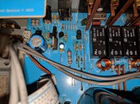
Now...I have a question for you if you still have the unit torn down. Can you please tell me what's in R401 on the R CH? The schematic calls for a 470 ohm resistor, but I had a jumper there. R301 on the L CH was populated with a 470 ohm resistor. These I believe are assembled in China...perhaps a mistake by an assembler. Thx.
Just an update to my own question...I have the V4 board and it has a resistor slot, R250, for the R CH at the mainboard preamp output, which is not shown on the schematic. So the power amp board input resistor, normally at R401, was instead soldered on the mainboard @ R250 and a jumper was placed in R401. As one can see by the image, I've relocated the resistor to the amp board and jumpered R250.

Just an update to my own question...I have the V4 board and it has a resistor slot, R250, for the R CH at the mainboard preamp output, which is not shown on the schematic. So the power amp board input resistor, normally at R401, was instead soldered on the mainboard @ R250 and a jumper was placed in R401. As one can see by the image, I've relocated the resistor to the amp board and jumpered R250.
Hey Rjsalvi,
I just back around to this restoration project this weekend
after almost a 1-year hiatus because of life Let me know if there's anything you want me to compare with - because I will continue the restoration project.
Thanks for the information and suggestions above, I will keep at it and build a dim-bulb tester. I just replaced all the electrolytic caps on the L Channel Amp Board, and I'm going component-by-component to discover anything fried. A long process...
Raj
- Status
- This old topic is closed. If you want to reopen this topic, contact a moderator using the "Report Post" button.