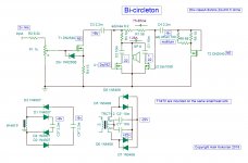
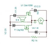
If you mean bi-circlotron, I don’t think it is a circlotron topology. Circlotron would require the output to be floating with respect to GND. The outputs are tied to GND and so is one terminal the speaker. If I unwrapped this and moved everything to the left, you are left with a SE Class A with a CCS made up of the right side (albeit with a twist) with a depletion mode n-channel MOSFET input stage (mimicking an N-JFET).
I think a true circlotron requires dual isolated power supplies, no fixed GND on speaker.
But, that doesn’t mean this isn’t a good sounding design - it’s nice to see alternative to JFET on input.
I think a true circlotron requires dual isolated power supplies, no fixed GND on speaker.
But, that doesn’t mean this isn’t a good sounding design - it’s nice to see alternative to JFET on input.
Last edited:
Did look familiar, i have seen something like that before 
Circlotrom,pootje meer want anders - forum.zelfbouwaudio.nl
Mona
Circlotrom,pootje meer want anders - forum.zelfbouwaudio.nl
Mona
Most beautiful sounding amplifier.
Hi Kokoriantz!
Clever!
Why did you choose DN2540?
Thank you padamiecki for being interested with this amplifier . If you look on page 5 of the datasheet transfer characteristics curves , you see at 100ma bias gets an inflation point . At this point it becomes very low distortion but of odd order . Adjusted by ears compared to 300B amp ,it gives extraordinary resemblance at 75ma to 85ma depending to the heat sink size . I can even say in many aspects the bi-circleton is more pleasant. I am preparing a layout PCB as Meanman1964 requested , I'll post on YouTube a comparative listening with 300B/2A3C in about 2 months .
Hajj ,my greetings from Vietnam.
Hajj ,my greetings from Vietnam.
Another solid triode ?
Thanks for sharing this information.
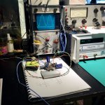
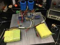
I haven’t build the whole bicycle yet, just a mono wheel, very impressive performance.
Regards from Pascal
. . .If you look on page 5 of the datasheet transfer characteristics curves , you see at 100ma bias gets an inflation point . . .
Thanks for sharing this information.
I haven’t build the whole bicycle yet, just a mono wheel, very impressive performance.
Regards from Pascal
Attachments
Last edited:
This amp is dc coupled. The capacitors are the reservoir electrolytic capacitors of the power supply . You can replace in the circuit by batteries if you prefer .
Warning with DN2540N5 . As mosfet it is sensitive to electrostatic. Before soldering short the pins with an aluminum foil or wire at the base . Just touching the gate with non isolated soldering iron the gate channel junction got leakage.
Warning with DN2540N5 . As mosfet it is sensitive to electrostatic. Before soldering short the pins with an aluminum foil or wire at the base . Just touching the gate with non isolated soldering iron the gate channel junction got leakage.
It's a push-pull gain stage with I-V conversion in signal path, capacitive coupling and floating PSU.
What's the purpose? Making simple things hard to make.
the amp is fine, I like it very much!
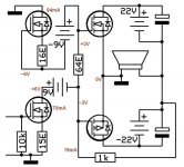

The output circuit explained
This output circuit is described in details along other complimentary ones in any electronic textbook in the future . Consider first just a pair of complimentary mosfets biased at 1.3A and 8 ohms load. Each mosfet has a trans conductance of 1 A/V , if 1 volt is applied on the gates by a voltage source it develops 16 volts on 8 ohms load , voltage gain=16 .
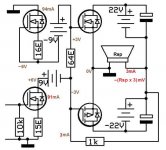
The transistors has a total input capacitance of 2.3nF ,made of 1.5nF gate-source and total reverse 50pF x (gain+1) . The load sees the ouput as high impedance of 750pF . Loudspeakers are designed to function with low impedance outputs which should not exceed one tenth of the speaker's cooper resistance . Nowadays they are as low as 5 ohms . By adding a reverse resistor of 1khoms and driving the amp by a high impedance current source , every volt that the speaker utters is heard 5/5 by the gates which in turn answers with a current in reason of 2A/V , the speaker now sees the output as 0.5ohms . As the frequency goes higher the input capacitance of 2.3nF deafens the gates and above 70khz the output impedance becomes inductive of 1.13uH . This is unique among amplifiers to have a single pole with asymptote phase shift of 90°. It will require a parasite capacitor of 4uf to provoke an overshoot of Q=1 on square wave. Such robust output does not need any Zobels .
If 1volt of output from this amp is demanded, it must provide a current of 1/8 A and about 1ma for the reverse resistor , gates voltage is to become 62.5mv, after which ,the voltage across the 1kohms reverse resistance to be 1.0625V . The input current source has to inject 1.0625ma to have 1V output ,this gives a trans resistance of 941ohms or 0.941A/ma . The input current source now sees the input impedance as 62.5 ohms shunted by 2.3nF input capacitance which results a frequency responce of 1.15Mhz always of single pole 6db/octave instead of 2 as in other amplifiers .As it doesn't have slew rate limitation, the power bandwith is also 1.15Mhz.
At 1W it has 0.002%Td (sim). This unique transfer function alied with the output impedance, is the reason for the exceptional voice of this amplifier . If BJT transistors having beta of 100 were used ,it would required 100ohms reverse resistance , with 10 times more driving current. This amp can perfectly function in class AB with bias current of 150ma , but the trans conductance of the mosfets becomes 0.5 each, resulting output impedance of 1 ohms suitable for 16 ohms load but 60 watts power ,0.02%Td at 1W ,500khz fr with 2.2kohms reverse resistor . Just adding 6db NFR to accommodate 8 ohms load, and the charming voice evaporates.
Kokoriantz
Katje,thank you for your help.
This output circuit is described in details along other complimentary ones in any electronic textbook in the future . Consider first just a pair of complimentary mosfets biased at 1.3A and 8 ohms load. Each mosfet has a trans conductance of 1 A/V , if 1 volt is applied on the gates by a voltage source it develops 16 volts on 8 ohms load , voltage gain=16 .
The transistors has a total input capacitance of 2.3nF ,made of 1.5nF gate-source and total reverse 50pF x (gain+1) . The load sees the ouput as high impedance of 750pF . Loudspeakers are designed to function with low impedance outputs which should not exceed one tenth of the speaker's cooper resistance . Nowadays they are as low as 5 ohms . By adding a reverse resistor of 1khoms and driving the amp by a high impedance current source , every volt that the speaker utters is heard 5/5 by the gates which in turn answers with a current in reason of 2A/V , the speaker now sees the output as 0.5ohms . As the frequency goes higher the input capacitance of 2.3nF deafens the gates and above 70khz the output impedance becomes inductive of 1.13uH . This is unique among amplifiers to have a single pole with asymptote phase shift of 90°. It will require a parasite capacitor of 4uf to provoke an overshoot of Q=1 on square wave. Such robust output does not need any Zobels .
If 1volt of output from this amp is demanded, it must provide a current of 1/8 A and about 1ma for the reverse resistor , gates voltage is to become 62.5mv, after which ,the voltage across the 1kohms reverse resistance to be 1.0625V . The input current source has to inject 1.0625ma to have 1V output ,this gives a trans resistance of 941ohms or 0.941A/ma . The input current source now sees the input impedance as 62.5 ohms shunted by 2.3nF input capacitance which results a frequency responce of 1.15Mhz always of single pole 6db/octave instead of 2 as in other amplifiers .As it doesn't have slew rate limitation, the power bandwith is also 1.15Mhz.
At 1W it has 0.002%Td (sim). This unique transfer function alied with the output impedance, is the reason for the exceptional voice of this amplifier . If BJT transistors having beta of 100 were used ,it would required 100ohms reverse resistance , with 10 times more driving current. This amp can perfectly function in class AB with bias current of 150ma , but the trans conductance of the mosfets becomes 0.5 each, resulting output impedance of 1 ohms suitable for 16 ohms load but 60 watts power ,0.02%Td at 1W ,500khz fr with 2.2kohms reverse resistor . Just adding 6db NFR to accommodate 8 ohms load, and the charming voice evaporates.
Kokoriantz
Katje,thank you for your help.
Attachments
This amp is dc coupled. The capacitors are the reservoir electrolytic capacitors of the power supply . You can replace in the circuit by batteries if you prefer .
...
You have very peculiar way of drawing and explaining things... very strange full wave rectifiers. Not sure if double diodes are needed for decoupling (prevention of circulating currents) etc. Still floating PSU is no good regardless to whatever claims you have, it can't produce decent S/N due to capacitive coupling between floating sources.
As others mentioned it's a CFB kin so what makes if "new" per say?
Is there a specific purpose of claiming it new?
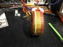
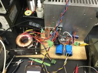
Main wheel
The whole bicycle is running (without 1 k resistor) on Aarta.
Go to bed now, will put a 1k in and going to build a transformer with copper shield for the 9V coil by tomorrow.
Cheers and
Thanks again Mr K
Thanks for sharing this information.
I haven’t build the whole bicycle yet, just a mono wheel ...
The whole bicycle is running (without 1 k resistor) on Aarta.
Go to bed now, will put a 1k in and going to build a transformer with copper shield for the 9V coil by tomorrow.
Cheers and
Thanks again Mr K
Attachments
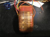
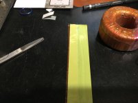
9V coil ES shield
Well, it had to be done twice.
First attempt failed due to overlap foil shorted, unwound 100 turns.
Second attempt with much more thicker tape insulation, rewound 100 turns, job done.
Well, it had to be done twice.
First attempt failed due to overlap foil shorted, unwound 100 turns.
Second attempt with much more thicker tape insulation, rewound 100 turns, job done.
Attachments
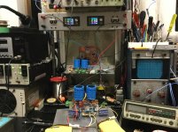
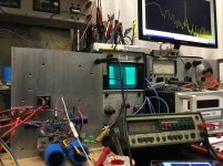
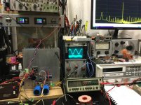
C3 - C4 2.2m not enough!
First disappointment , on floating rectified 9V supply, without 1k R feedback, my bicycle is oscillating.
Second disappointment, 50Hz is -40dB at the output, it was reduced to -60dB with C-R add on (10mF and 2.7R)
First disappointment , on floating rectified 9V supply, without 1k R feedback, my bicycle is oscillating.
Second disappointment, 50Hz is -40dB at the output, it was reduced to -60dB with C-R add on (10mF and 2.7R)
Attachments
- Status
- This old topic is closed. If you want to reopen this topic, contact a moderator using the "Report Post" button.
- Home
- Amplifiers
- Solid State
- bi-circleton