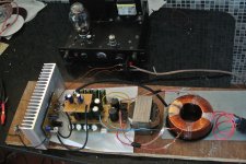
SMPS versus Linear PS
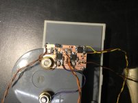
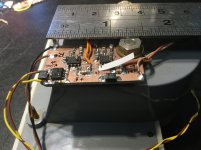
The amp doesn’t sound right, compared to the prototype that it was run on batteries, perhaps the voltage was higher (12.6V 3S lithium x 2) than the 9Vac rectified supply.
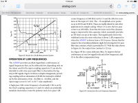
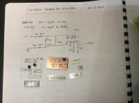
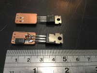
The spec of DN2540 shows at 10Vds, we have a very linearity of ~80mA/V in the region from 0 to 60mA.
With 9Vac rectified supply, Vds is merely about 5V, wander that would be the cause, need an effort to simulate and breadboard the DN in that region.
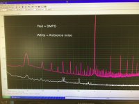
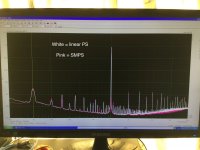
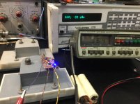
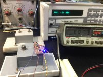
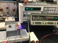
Another breakthrough, for sure I am a laughingstock, the same amp, running on SMPS and Linear Supply, provides the same spectrum of 1kHz signal injected, one can’t tell the difference, but can hear a very distinct sound for the same piece of music, Linear Supply is the winner (I will modify the SMPS current limiter to bypass the current 2A limit, perhaps 2.5A and add more capacitance to the bank, stubbornly I don’t want to be a laughingstock).
The amp doesn’t sound right, compared to the prototype that it was run on batteries, perhaps the voltage was higher (12.6V 3S lithium x 2) than the 9Vac rectified supply.
The spec of DN2540 shows at 10Vds, we have a very linearity of ~80mA/V in the region from 0 to 60mA.
With 9Vac rectified supply, Vds is merely about 5V, wander that would be the cause, need an effort to simulate and breadboard the DN in that region.
Another breakthrough, for sure I am a laughingstock, the same amp, running on SMPS and Linear Supply, provides the same spectrum of 1kHz signal injected, one can’t tell the difference, but can hear a very distinct sound for the same piece of music, Linear Supply is the winner (I will modify the SMPS current limiter to bypass the current 2A limit, perhaps 2.5A and add more capacitance to the bank, stubbornly I don’t want to be a laughingstock).
Attachments
Off course Linear wins...
Cheers
Not yet, back to SMPS with modified voltage and current sensor.
Will leave the amp as it is and go back to the prototype to learn more about the driver.
Cheers
YouTube
Today I work on the fascia, mounted two dB meters, a question in my mind, what is for?, perhaps “noblesse oblige”...
Well, the Vu meters swing like a cold turkey, despited the fact that they were pulled out from lab equipments.
Have you ever heard about selenium rectifier? I use it to rectify the speaker voltage for the meter movements. Not good at all, should use germanium diode or fast schottky’s.
I think about a log amplifier that would bring justice to a 13” meter face. Couldn’t find any suitable diodes, so I use a pair AD8307 that I found in my shed. It is an RF component, that help me not infringing that only non audio components should used in this design (exception for lateral mosfet).
The sot adapter from EBay won’t match the AD8307, so I strained my eyes to scribe 2 log amps from a scratch of FR4 copper glad.
Cheers
Attachments
AD8307 Vu-Meter alignment
The pair is working like a train, from -99dBm to +20dBm.
The only mistake is a cross interference between two channels, will scribe another board for separation and both amps will be shielded.
How much accuracy that I can relying on, due to the previous owner of my generator who had done a calibration in 19-oct-2001.
Cheers
Attachments
AD8307 beats them all
Well, so clumsy as I am, I found my mistake, the right log amp IC, pin 1 “input” is connected to pin 5 of the left log amp, i though that pin 5 was listed as “nc” nothing there, just a dummy’s pin, in fact that pin creates a crossed interference.
Lift up all pins 5, no need shield nor separation, the AD8307 beats them all.
Another problem arisen, my meter got -20 to +3 dB scale, the AD8307 has -90 to +20 dBm range, what should I do, all suggestions are welcome!
Cheers
YouTube
Between us:
I am cheating, the AD8307 is able to detect my -70dB 50Hz ripple and its multiples.
The log amps put out a dc voltage of 0.36V, that moves my meter to a scale of -7dB (nearly 1/6th of its movement).
To hide this defective (while waiting to solve my ripples problem) I connect the AD8307 to the input of my amp!
Easy problem solved!
Attachments
Last edited:
Looking good & sounding good too Mosfet. Was looking the the schematics again. So basically for this design we need a trafo with 2 windings of 0-20v for each channel right so may I ask why do you need a seperate shield 9v supply for the input ? Can it not be say a normal split bobbin trafo ?
Thks
Thks
Thanks Mosfet yes I understand the required voltage but do you ise trafo with CT or ???? The PS schema seems to show otherwise.
Thks
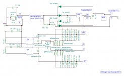
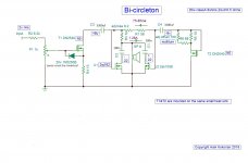
I don’t used transformateur with CT, mine is based on SMPSs, the CT is a common link between 2 SMPS units that goes to the speaker + terminal.
The PS schéma not showing any dissimilarity rather than an insertion of a phase reversal dual coils choke.
It’s purposed is to reduce the ripple output voltage by choking AC components and store that wasted energy in the choke’s core as extra magnetic flux for releasing at next AC phase.
It’s a very efficiently DC supply for less Filter capacitances.
Hope that my interpretation is correct.
Cheers
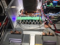
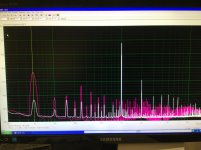
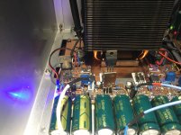
Huge Band-Aid
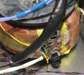
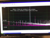
Unable to reduce AC ripples for my driver, I go back to my initial attempt by using C - R - C - R - C to achieve a -80dB floor noise.
Well, it is huge, 16 x 8mF caps and and 16 2R2 resistors.
I think that The original Bi-Circleton used only 2mF dues to the secret phase cancellation for using a single toroidal transformer, will tryout this week.
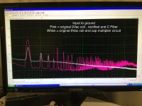
The pinky curve was my attempt with 2mF filtering.
The white, 16 x 8 caps, is a signature of my Bi-Circleton
Cheers
Unable to reduce AC ripples for my driver, I go back to my initial attempt by using C - R - C - R - C to achieve a -80dB floor noise.
Well, it is huge, 16 x 8mF caps and and 16 2R2 resistors.
I think that The original Bi-Circleton used only 2mF dues to the secret phase cancellation for using a single toroidal transformer, will tryout this week.
The pinky curve was my attempt with 2mF filtering.
The white, 16 x 8 caps, is a signature of my Bi-Circleton
Cheers
Attachments
hum buzz & Co
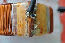
I modified the power supply . To reduce the 50hz residual , the low level is installed on a separate board , To go shick I added a pair of 9v regulators, by this ,any thin wire wound to give 12-13 volt ac can work . I simplified the shield to single layer with sloted printed circuit as intoduced by MosFed . The problem with this ,the shield bears one turn volt between it's endings . Two identical resistors of 10 ohms can make an equipotential point to hook the earth . The shield is isolated by four layers of isolating ribbon used for packaging gift or flower motif, the winding is done with less than 5mm wide footprint . As the shield has more capacitance on the beginning windings B than the endings E ,if voltage is measured by a 1M ohms multimeter , it reads 1.4v shield to B and 7v shield to E . A 33pf capacitor on E to shield brings the two voltages near equal ,but a trim capacitor on the board adjusts the difference of B,E measured from ground to any of four supply ,to 00.0 mv . To remind that one mv at this point pollutes the output by 1uv . Similarly the main 20v windings receive 5.7nf and 3.9n with 1k in series to ground to reduce the hum and buzz to less than 40mv difference. Here 2v differnce pollutes the output with 1uv . The electrolytic capacitors of 3300uf on the amplifier circuit board acquire the two 9v . By this methode the output noise measured by the multimetre 200mv ac scale measured 00.0 mv that is less than 50uv noise .
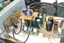
The main power supply got modified with serie resistors on the capacitors ,whereas the inductor proposed on Aliexpress turned out to be 5.2mh and not 50mh as advertised , and with 1.3A measured 0.57mh ,in other words useless for this powersupply. I converted a 48VA power supply transformer with EI76 stacked 40mm to mutual inductor by winding 1.2mm thick wire in bifilar (two wires in hand ) 60 turns to fill the bobine . The result is 0.15 ohms per winding and 37mh(two windings in series) at 1.3A with airgap of 5 microns. The rquired inductance is 56mh minimum . For remedy I will replace the iron core with a higher silicon content .
At this stage the amplifier excels the 300B ,enhanced to 2A3C at all aspects except bellow 40hz , the lowest note of the double C .
I modified the power supply . To reduce the 50hz residual , the low level is installed on a separate board , To go shick I added a pair of 9v regulators, by this ,any thin wire wound to give 12-13 volt ac can work . I simplified the shield to single layer with sloted printed circuit as intoduced by MosFed . The problem with this ,the shield bears one turn volt between it's endings . Two identical resistors of 10 ohms can make an equipotential point to hook the earth . The shield is isolated by four layers of isolating ribbon used for packaging gift or flower motif, the winding is done with less than 5mm wide footprint . As the shield has more capacitance on the beginning windings B than the endings E ,if voltage is measured by a 1M ohms multimeter , it reads 1.4v shield to B and 7v shield to E . A 33pf capacitor on E to shield brings the two voltages near equal ,but a trim capacitor on the board adjusts the difference of B,E measured from ground to any of four supply ,to 00.0 mv . To remind that one mv at this point pollutes the output by 1uv . Similarly the main 20v windings receive 5.7nf and 3.9n with 1k in series to ground to reduce the hum and buzz to less than 40mv difference. Here 2v differnce pollutes the output with 1uv . The electrolytic capacitors of 3300uf on the amplifier circuit board acquire the two 9v . By this methode the output noise measured by the multimetre 200mv ac scale measured 00.0 mv that is less than 50uv noise .
The main power supply got modified with serie resistors on the capacitors ,whereas the inductor proposed on Aliexpress turned out to be 5.2mh and not 50mh as advertised , and with 1.3A measured 0.57mh ,in other words useless for this powersupply. I converted a 48VA power supply transformer with EI76 stacked 40mm to mutual inductor by winding 1.2mm thick wire in bifilar (two wires in hand ) 60 turns to fill the bobine . The result is 0.15 ohms per winding and 37mh(two windings in series) at 1.3A with airgap of 5 microns. The rquired inductance is 56mh minimum . For remedy I will replace the iron core with a higher silicon content .
At this stage the amplifier excels the 300B ,enhanced to 2A3C at all aspects except bellow 40hz , the lowest note of the double C .
Attachments
...
Regulated supply, or much better is “cap multiplier” is degrading the elegance of the circuit.
Hi Mr K,
With my thought that you can pull a rabbit out of a hat, I was waiting to learn your trick to neutralise the 50 Hz residuals.
Thanks for your revelation, an 7809 is the ultimate weapon.
I run out of any 78xx, only a pair of 2SD116, a quick and dirty cap multiplier was built.
The result is impressive, although it is useless due to 4V loss.
Will rewinding the 9Vac coil with ample voltage headed, RC shield neutral circuit and using an LDO as cap multiplier.
Arta test was done with signal input grounded and output was connected to soundcard input via 8 Ohm dummy load.
For unknown reason, the floor noise is risen up 20dB?
Cheers
Attachments
Hi Mr K
I’ve been following Mosfet build on the amp & would also like to thank you for sharing your design. What Im trying to understand is the shielding of the power supply & the thin wires that you’ve recommended. Is the circuit this sensitive to noise pick up etc ? If I use 2 trafo, one for output & one for the 9v supply & with enough capacitance will this not be sufficient to reduce noise ?
Thank you
- Status
- This old topic is closed. If you want to reopen this topic, contact a moderator using the "Report Post" button.
- Home
- Amplifiers
- Solid State
- bi-circleton