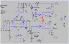
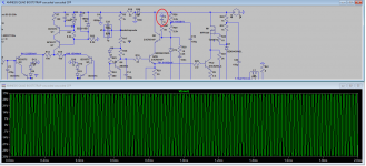
Hi Max,Guys, I revisited my crazy alternate compensation scheme on the Darlington output amp. It behaves well on square wave test and in stability terms, IMHO.
Is there an explicit way to show stability margins in LTspice?
You know I am a nullity with LTspice: I've tried without luck to introduce the BD139/140.
I hope today I will have time to complete my test with the last configuration proposed as optative oscillation killer: 50R-10nF from base to ground of the driver's cascode.
Cheers,
M.
Using a square wave is my favourite way to test stability.
Drive your design to the limit in terms of bandwidth and find out where it goes wrong.
This means lowering the Miller cap to see when it starts to become unstable and go a little bit above this value.
Then look at all the currents through resistors and see if there are larger in and outswing oscillations as expected.
Try to find out what causes this by changing component values.
Also try to oversteer the amp and see what happens. This could also cause serious oscillations and needs a different approach to solve.
When going to use the BD139/BD140 you certainly have to get the system stable with them inserted.
When everything meets to your satisfaction, you can again increase the Miller cap to its original value.
Hans
Hi Max,
Using a square wave is my favourite way to test stability.
Drive your design to the limit in terms of bandwidth and find out where it goes wrong.
This means lowering the Miller cap to see when it starts to become unstable and go a little bit above this value.
Then look at all the currents through resistors and see if there are larger in and outswing oscillations as expected.
Try to find out what causes this by changing component values.
Thanks! I did exactly that to find the 50R-10n decoupling.
") Though I still find some crazy currents of the supposedly non-harmful 10R-100n between bases of cascodes...
Though I still find some crazy currents of the supposedly non-harmful 10R-100n between bases of cascodes... Also try to oversteer the amp and see what happens. This could also cause serious oscillations and needs a different approach to solve.
When going to use the BD139/BD140 you certainly have to get the system stable with them inserted.
When everything meets to your satisfaction, you can again increase the Miller cap to its original value.
Hans
I tried to oversteer with a 1.8 v 10Khz Sinuswave, an oscillating disaster.
Too bad. But at least you gave me a tool to test my decouplings
Lets try again.
M.
Ah! OK. I will try it.
As I said, I am not an expert on Darlington so I need you guys to optimize the options...
So far my last "QUAD" is sounding very decent, as my mom says
That one is the recommended version, though, JOSI1 marvelous PCB will allow each one of the costumers to try by themselves the following options:
1) Input: standard CFP (different resistor arangement/vaues) v/s cascoded-CFP AKA cacode-inside-CFP...probably DC offset readjust needed
2) VAS:
a.- simple cascoded common emitter VAS v/s cascoded emitter follower VAS.
b.- bootstrap loaded VAS v/s CCS loaded VAS.
3) Drivers: simple v/s bootstrapped drivers...apart playing with different transistors brands/models. Bootstrapping with MOSFETs, as we did with the outputs??? Medium power MOSFETs (or JFETs) required...
4) Several output arrangements from which to choose : simple EF; simple driver with bootstrapped output (mentioned above); bootstrapped Darlington; bootstrapped Sziklai output; "TRIPLE" OUTPUT; "QUAD" output; "QUAD" with VFETs
All in all, an oscillation dream 
The truth is that my limited skills are exhausted but "I'll get by with a little help from my friends". Seriously, my hope is that, when the PCBs are ready, and if this diamond in the raw is considered worthy of your attentions, I am sure we would be able to refine the beast and end with a pure musical bliss conveying amplifier.
Cheers,
M.
As I said, I am not an expert on Darlington so I need you guys to optimize the options...
So far my last "QUAD" is sounding very decent, as my mom says
That one is the recommended version, though, JOSI1 marvelous PCB will allow each one of the costumers
to try by themselves the following options:1) Input: standard CFP (different resistor arangement/vaues) v/s cascoded-CFP AKA cacode-inside-CFP...probably DC offset readjust needed
2) VAS:
a.- simple cascoded common emitter VAS v/s cascoded emitter follower VAS.
b.- bootstrap loaded VAS v/s CCS loaded VAS.
3) Drivers: simple v/s bootstrapped drivers...apart playing with different transistors brands/models. Bootstrapping with MOSFETs, as we did with the outputs??? Medium power MOSFETs (or JFETs) required...
4) Several output arrangements from which to choose
: simple EF; simple driver with bootstrapped output (mentioned above); bootstrapped Darlington; bootstrapped Sziklai output; "TRIPLE" OUTPUT; "QUAD" output; "QUAD" with VFETs All in all, an oscillation dream
The truth is that my limited skills are exhausted but "I'll get by with a little help from my friends". Seriously, my hope is that, when the PCBs are ready, and if this diamond in the raw is considered worthy of your attentions, I am sure we would be able to refine the beast and end with a pure musical bliss conveying amplifier.
Cheers,
M.
Last edited:
Dear Hans Polak wrote:
Man, that is not the way to treat an amp!
Clipping torture...
Tools, tools, I need more tools and learn how to use them
Cheers,
M.
I tried to oversteer with a 1.8 v 10Khz Sinuswave, an oscillating disaster.
Man, that is not the way to treat an amp!
Clipping torture...
Tools, tools, I need more tools and learn how to use them
Cheers,
M.
Hi Max,
looks like a greatly simplified circuit, but I think you are missing the output device switch off network.
Regards
Symon
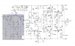
Thanks to Symon's advice, it seems much better now.
My two Amnesis "QUAD bootstrap" are runing fine with slightly different decoupling for the drivers' bootstraps, so basically it would be a matter of adjusting if ever it oscillates. The last published schematic is valid, with 10n-small R (50R or lower) shall do fine.
Apart, I have both mixed (2SC4793/BD139-2SA1837/BD140) and same unit (2SC4793*2 and 2SA1837 *2) botstrapped pairs in the drivers section: same unit might be more stable (as none as failed to date) and tend to produce thicker, more robust sound.
Cheers,
M.
Attachments
Last edited:
Hi Max,
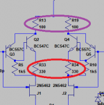
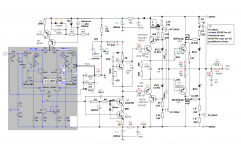
something that I've wondered about for a while is why the emmitter feed back values for Q2 and Q4 (R33 & R34) are 3 times the value of the overall feedback resistors R13 & R19.
The current through Q2 & Q4 is much higher than through Q3 & Q5.
Subjectively I feel that reducing these values will reduce the loading on Q3 & Q5 and as these control the overall feedback there performance is critical.
In many CFP circuits R13 and R19 are zero ohms. I'd be reluctant to reduce them to zero here in case it introduces instablility, but would be interestng to see what reducing R13 & R19 to say 100 ohms does to the sound.
Regards,
Symon
Attachments
Hi Max,
something that I've wondered about for a while is why the emmitter feed back values for Q2 and Q4 (R33 & R34) are 3 times the value of the overall feedback resistors R13 & R19.
The current through Q2 & Q4 is much higher than through Q3 & Q5.
Subjectively I feel that reducing these values will reduce the loading on Q3 & Q5 and as these control the overall feedback there performance is critical.
In many CFP circuits R13 and R19 are zero ohms. I'd be reluctant to reduce them to zero here in case it introduces instablility, but would be interestng to see what reducing R13 & R19 to say 100 ohms does to the sound.
Regards,
Symon
Exactly.
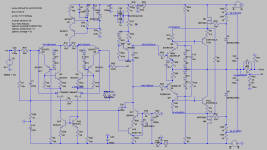
That is the option I mentioned and that is why I recommend connection pins in all critical resistor parts: R33-R34 could be changed from 0 to 500 Ohm and R5-R19 from 1K to 2K7 to see if there is a perceptible change, both measured (for those who have the instruments) and/or on sound quality. Dr. Kolinummi talks about putting a CCS in place of R33-R34, if I remember correctly.
Now that the Bootstrapped Darlington output version seems feasible, I am trying to get a stable version of the Bootstrapped Sziklai output version,
the only reason to split (R2-R20) drivers' emitter resistors...I confess I am partial to the "slower" power BJTs' bootstrapped output, the MJE15024-25, over the 5200/1943...but these are not the only differences between the two amps so I cannot be completely sure they are superior sounding devices, in this configuration. For that I will need two identical amps (safe the mentioned) and PSs.
Cheers,
M.
Hi Max,
I didn't do any listening tests but made intensive tests concerning stability/oscillations.
Test configuration
Ups=+-33V from Lab supply with Imax=+-5A
Rl= 8R and 4R
darlington output with bootstrapping
driver transistors BD139/BD140
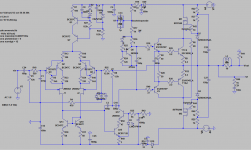
Input and VAS acc.to QUAD schematic (new input stage not used)
see Testreport1 and Testreport2 for results
Cheers
BTW, JOSI1, did you listened to your single channel? And, is it stable? Just curious...anyhow, at least 48hrs of burning-in are recommended before critical listening.
I didn't do any listening tests but made intensive tests concerning stability/oscillations.
Test configuration
Ups=+-33V from Lab supply with Imax=+-5A
Rl= 8R and 4R
darlington output with bootstrapping
driver transistors BD139/BD140
Input and VAS acc.to QUAD schematic (new input stage not used)
see Testreport1 and Testreport2 for results
Cheers
Attachments
Hi Max,
I didn't do any listening tests but made intensive tests concerning stability/oscillations.
Test configuration
Ups=+-33V from Lab supply with Imax=+-5A
Rl= 8R and 4R
darlington output with bootstrapping
driver transistors BD139/BD140
Input and VAS acc.to QUAD schematic (new input stage not used)
see Testreport1 and Testreport2 for results
Cheers
Hi JOSI1,
This is great work. Thank you very much for believing in my crazy ideas.
At first glance I see a widening of the trace at negative peak of the 100KHz sine, which may be caused by VHF oscillations. Try to increase gate stopper resistor for the P channel MOSFET until it disappears. For example 300R and then down, if successful...
Edit: look at the trace at lower output and see if the output becomes symetric and with slim traces...that would confirm hypothesis of oscillations on peaks due to probable local resonance...
Also, I would try lower value inter-emitter driver resistor and see what happens.
I am trying new ideas for the Sziklai output and I also found classic Miller equal or better than my crazy alternative comp.
More on this Sziklai later.
Best wishes,
M.
Last edited:
Hi again JOSI1,
I forgot to ask, what values of Miller cap do you used?
Perhaps a lower value might work better in your case.
What bias current do you used?
Can you check the VAS behavior in your 100KHz test?
Apart, thinking about a local resonance problem, other trick can be adding ferrites in parallel with the output units bases' and gates' resistors, or increasing the values of those resistors. Another trick we have not tested is making power emitter resistors slightly asymmetrical, like 0R3 NPN and 0R47 PNP.
Anyway, for quick connections I use a sort of "wire wrapping" connection, for easy soldering and de-soldering, while testing different resistor values on those bases...
I keep checking the PCB diagram. So far no mistakes found regarding connections, only some comments on alternative values.
Best wishes,
M.
Hi Max,
I use a Miller Cap of 100p, lowering the cap does not improve stability.
Lowering the value of inter-emitter driver resistor to 33 Ohm and
increasing the gate stopper resistor for the P channel MOSFET to 150 Ohm
keeps the amp stable at any input frequency.
Due to little board space in this area I removed the alternative compensation.
Input stage
On my test amp I use R5/R10=1k5 and R33/R34=0.
If I increase R33/R34 step by step offset voltage rises (could be adjusted ) but mainly is fluctuating. The limit would be 47 Ohm, 330 Ohm does not work at all.
Cheers
Hi Max,
I use a Miller Cap of 100p, lowering the cap does not improve stability.
Lowering the value of inter-emitter driver resistor to 33 Ohm and
increasing the gate stopper resistor for the P channel MOSFET to 150 Ohm
keeps the amp stable at any input frequency.
Great news.
While the "QUAD bootstrap" is giving faithful musical service (I believe I achieved my goal of transparency and dynamic contrasts) I simulated it with your 100KHz signal and it also collapses and distorts the signal after 3 cycles. With 0.3V/50KHz input sine it goes OK at least for 1ms, if I remember correctly. Intermediate values give maybe ten good signal outputs and then it collapses...I've been trying to figure out where is the limiting step.
Due to little board space in this area I removed the alternative compensation. OK
Input stage
On my test amp I use R5/R10=1k5 and R33/R34=0.
If I increase R33/R34 step by step offset voltage rises (could be adjusted ) but mainly is fluctuating. The limit would be 47 Ohm, 330 Ohm does not work at all.
Cheers
Do you see some changes in behavior between R33-34 values?
I use a big value (5K) pot in parallel to one of the current mirror emitter's resistor (68R) to null offset. The chosen 68R will depend on the polarity of the offset, if I remember correctly.
Of course one could match active devices or cascode the mirrors as we used to in simulations. Maybe that would lower offset.
Apart:
About the optional small cap // feedback resistor, using four 50K resistors in // will give some capacitance. Value will depend on the size I imagine. I will see if I can measure it with my Chinese transistor tester.
I bought a cheap signal generator for my "free energy" experiments but I saw that it produces HF spikes in square or triangle shapes so maybe won't be good for testing my "QUAD positive feedback amp"
Today "Parrillada season" opens
and I will have a few free days so I may be able to finish revision work.Best wishes,
M.
Attachments

Today "Parrillada season" opens and I will have a few free days so I may be able to finish revision work.
The following is an updated image of what a Chilean parrillada should look like...we usually cook 3 or 4 different kind of meats and sausages simultaneously.
Attachments

The following is an updated image of what a Chilean parrillada should look like...we usually cook 3 or 4 different kind of meats and sausages simultaneously.
Can you send me the .asc file of this mouthwatering meat ?
Can you send me the .asc file of this mouthwatering meat ?
The virtual world is not as tasty as the "real" one, I'm afraid...and experience is not transferable.
I looked for the translation and it says "Tenderloin Beef", it is Ox meat with good fat infiltration, with a prolonged stay in vacuum to keep it soft, at USD $10 per Kilo.
it used to be USD $7 until I (and others) discovered it I can provide the easy recipe. This is one of my 10 hobbies, but I haven't realized it...
Look, I found a good Xmass present, useful for children and for members of any forum.
Attached.
On a more serious topic, I've been thinking about the "filter" for the input-VAS section, which I copied from the Blame (not exactly as that amp has 47n to ground) and I asked myself, will a snubber for the diode be helpful? Perhaps not, given that the ripple shall be low...what do you guys think.
Best wishes,
M.
Attachments

I found the culprit of the problem mentioned with 100KHz signal distortion:
The culprit is the 10nF bypass cap for the boostrapped BJT (C3 and Q8 in the simulation) which is replaced by 1nF to make a good near-clipping response for 2ms at least. I have not tested in real life if such a small cap would still make the amp stable.
The moral is: use the smallest cap that does stabilize the amp.
Sincerelly, I don't understand how you can refrain from building this very promising (and potentially unstable) amplifier.
Cheers,
M.
While the "QUAD bootstrap" is giving faithful musical service (I believe I achieved my goal of transparency and dynamic contrasts) I simulated it with your 100KHz signal and it also collapses and distorts the signal after 3 cycles. With 0.3V/50KHz input sine it goes OK at least for 1ms, if I remember correctly. Intermediate values give maybe ten good signal outputs and then it collapses...I've been trying to figure out where is the limiting step.
The culprit is the 10nF bypass cap for the boostrapped BJT (C3 and Q8 in the simulation) which is replaced by 1nF to make a good near-clipping response for 2ms at least. I have not tested in real life if such a small cap would still make the amp stable.
The moral is: use the smallest cap that does stabilize the amp.
Sincerelly, I don't understand how you can refrain from building this very promising (and potentially unstable) amplifier.
Cheers,
M.
Attachments
I think I may have found a working and stable Sziklai output.
I tested with all the tests you tought me (and more) and it behaved.
Now I have to find the time and energy to build it...
Apart:
Is there a way to make a Sziklai VAS???
Best wishes,
M.
I tested with all the tests you tought me (and more) and it behaved.
Now I have to find the time and energy to build it...
Apart:
Is there a way to make a Sziklai VAS???
Best wishes,
M.
Attachments
- Home
- Amplifiers
- Solid State
- The AMNESIS amp: a good amplifier, like a gentleman, has no memory.