Of course in your case it's the current output that counts, but I was just curious to repeat the test that Kolinummi describes in his book.Ah! very interesting. I tried to connect that way the second cascoded BJT but it cannot be done. Is it right to have a voltage output instead of a current output? Can they be compared?
And there was no overlap with my finding, so be careful to follow an unconfirmed advise.
Are you referring to a real measurement of the complete amp? In that case the cause might be that your Fets do not have a source voltage of -4.2 Volt but quite a bit less, leaving not enough room left to connect the gates to the emitters.Unfortunatelly, when I tried the gate-to-emitter mod on the "QUAD" the stability margin decreased and the THD deteriorated several orders of magnitude...
But when simulating, there is no visible difference between the two for a complete amp.
No, not the whole input stage arrangement is susceptible to TP, because Q3 and Q4 have full control.Anyway, isn't the whole arrangement (bootstrapped cascoded-CFP) susceptible to thermal analysis? Can you see what happens to the JFET?
As I understand, it is not the absolute value of thermal production but the alteration of it following the non constant musical signal. Maybe non-periodic bursts of square waves could show something useful...
And as explained in previous the TD sims, I was only looking at the effect of a periodic burst, the steady state power consumption was subtracted.
When looking for instance at the dual bootstrap image in #334, you will see in the top that 3.2155465mW was subtracted, being the steady state power consumption.
Hans
Are you referring to a real measurement of the complete amp? In that case the cause might be that your Fets do not have a source voltage of -4.2 Volt but quite a bit less, leaving not enough room left to connect the gates to the emitters.
But when simulating, there is no visible difference between the two for a complete amp.
Simulations only. I'm busy with other projects at the moment but I might try it later...
No, not the whole input stage arrangement is susceptible to TP, because Q3 and Q4 have full control.
And as explained in previous the TD sims, I was only looking at the effect of a periodic burst, the steady state power consumption was subtracted.
When looking for instance at the dual bootstrap image in #334, you will see in the top that 3.2155465mW was subtracted, being the steady state power consumption.
Hans
Now I understand better. Thank you very much for the explanation.
Then one of the versions shows no delta T° when pushed. Please upload the circuit that performs so well. Remember I have updated many times with the same name...
On the mean time, I made my mind about the non optimized "Bootstrapped-Darlington" output: on stock form it performs quite well and is much easier to stabilize and has much fewer parts than the "QUAD"; it is a tad less dynamic and little less defined, and it is "darker" sounding. To my amazement, when I performed the RDRD string mod, the focus and definition improved a lot, practically on par with the "QUAD". Unfortunately, it lacked instruments separation, depth of image and definition of the melodic lines compared to the official Amnesis, but I am sure it would be totally satisfactory for someone not acquainted with the best version.
I am not expert on Darlington circuit so I imagine it can be perfected...it is so simple that it would be a shame not to use it...Which takes me to the working hypothesis for the output (driver buffer and output section), which must be able to exploit the putative benefits of the input section (whichever the mechanisms involved) for which function it must be fast and linear and more...that lend me to explore cascodying and then bootstrapping, that apparently deals with Early effect (base width modulation) but also has a positive feedback effect by injecting the signal (or a buffered sample of it) to the base/gate. I detected a correlation between this bootstrap and dynamics: the more bootstraps in the amp, the more micro and macro-dynamics...and the more unstable it becomes
: I could be completely off here but it is nevertheless an interesting concept. Anyway, when you build the thing you will be able to analyze it with better equipment than that I have and listen to it and tell me that I am a complete fool or whatever you like
Best wishes,
M.
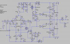
I have used these two versions, the Dual and the Triple Bootstrapped versions. See image below. From a thermal point of view, the Dual version performed much better.Now I understand better. Thank you very much for the explanation.
Then one of the versions shows no delta T° when pushed. Please upload the circuit that performs so well. Remember I have updated many times with the same name...
The most noticeable effect of bootstrapping is that Cbc will be carrying a very much smaller AC component, thereby decreasing the input capacity.Which takes me to the working hypothesis for the output (driver buffer and output section), which must be able to exploit the putative benefits of the input section (whichever the mechanisms involved) for which function it must be fast and linear and more...that lend me to explore cascodying and then bootstrapping, that apparently deals with Early effect (base width modulation) but also has a positive feedback effect by injecting the signal (or a buffered sample of it) to the base/gate. I detected a correlation between this bootstrap and dynamics: the more bootstraps in the amp, the more micro and macro-dynamics...and the more unstable it becomes
Anyway, when you build the thing you will be able to analyze it with better equipment than that I have and listen to it and tell me that I am a complete fool or whatever you like
Especially output drivers can have large (non linear) Cbc capacities that will be significantly reduced by bootstrapping, increasing the Bandwidth and reducing the distortion.
Hans
Attachments
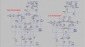
I have used these two versions, the Dual and the Triple Bootstrapped versions. See image below. From a thermal point of view, the Dual version performed much better.
The most noticeable effect of bootstrapping is that Cbc will be carrying a very much smaller AC component, thereby decreasing the input capacity.
Especially output drivers can have large (non linear) Cbc capacities that will be significantly reduced by bootstrapping, increasing the Bandwidth and reducing the distortion.
Hans
I see we have a nomenclature problem
When I speak about "double, tripple, quad" I mean it on an horizontal sense, for example, the "quad" has a bootstrap in every section of the amp and the "triple" has bootstraps in 3.
What you name as double is the original cascoded-CFP input but to conform to Kolinummi's nomenclature, it is a bootstrapped-CFP as the cascading element receives a sample of the signal. The one you name "triple" is bootstrapped cascoded-CFP (cascode-inside-the-CFP) and I was about to tell that it is funny that the one that behaves the worst on thermal terms is the most clean and open sounding...but yesterday I noticed that I blew again the driver's cascode for the positive side, so i have to investigate what is happening.
Best wishes,
M.
Hi Max,
I nearly finished a Combi Layout for experimentation based on your latest QUAD bootstrapp schematics covering the following configurations:
QUAD
TRIPLE bootstrap.
Darlington bootstrap
Cascoded SZIKLAI
all with CCS VAS and new input circuit.
The schematic pdf-file contains the 4 configurations high lighted in color.
The different configurations are realized by mounting options. Only the
Cascoded SZIKLAI requires cutting wires and reconnecting via solder bridges
(swapping collector/emitter the output transistors).
I know that the attached 2 layer layout is not easy check but I do my best that everything is correct.
I will explain the mounting options later in a separate document.
So concentrate on checking the attached schematics.
Cheers
Attachments
Hi Max,
I nearly finished a Combi Layout for experimentation based on your latest QUAD bootstrapp schematics covering the following configurations:
QUAD
TRIPLE bootstrap.
Darlington bootstrap
Cascoded SZIKLAI
all with CCS VAS and new input circuit.
The schematic pdf-file contains the 4 configurations high lighted in color.
The different configurations are realized by mounting options. Only the
Cascoded SZIKLAI requires cutting wires and reconnecting via solder bridges
(swapping collector/emitter the output transistors).
I know that the attached 2 layer layout is not easy check but I do my best that everything is correct.
I will explain the mounting options later in a separate document.
So concentrate on checking the attached schematics.
Cheers
Gott im Himmel!
You really managed to do all that?
I will check the best I can.
But you know there is a high risk of having to add a C and/or and R here and there due to probable local resonating tanks (fields
) , do you?Also, the gate stopper R could be increased a bit to achieve the same.
One of my Amnesis (Red PCB) needs at least one 100n from base to ground for the driver's cascode of the positive side: ongoing tests with different speakers.
Edit: this one has less than 5mV aperiodic oscillation of the base line, but I forget always to add the 100n from ground-to-heatsink trick.
The other one, the DIY PCB (copper upside) was perfectly fine with no extra caps but the other day I discovered the same position BJT (driver's cascode) was gone; since it went shorted the amp kept working though voltages were not good...I will investigate as time allows. That one has the cascode-inside-CFP (3 BJT- CFP) and 3 diodes to ground (BAS16J will be then: SOD323, right?) and was declared the most transparent and open of them all. The last days I found it sounded a bit on the clearer side, that's why I rechecked...
I am indebted to all my virtual friends that engaged in this crazy adventure of mine


I hope you will not be disappointed


Well, with all those configuration options you better not!
Cheers,
M.
Last edited:
Questions and comments to all my contributors:
1) What would be the minimal VDC capability of the bootstrap capacitors for +/-45 PS???
2) Are C35-C36 100n caps needed at all? Those parallel to the diode string from base to ground on the cascode-inside-CFP...
3) D21 and D22 are only needed for the CCS-VAS version.
4) the proposed input filters R4-C2 are different given the version of the amp and are based on my very limited understanding of safe stability margins (not to say non-existent) so any recommendation or experimentations is welcome.
Only that for the moment.
M.
Hi Max,
I added a C=100n from base to GND for the driver's cascode of the positive side.
VDC capability of the bootstrap capacitors
The DC voltage across the CAPs is constant /independant of output level.
The superimposed AC voltage is below 100mV and can be ignored.
Bootstrap CAP of BS-VAS
(identical Resistor values e.g.1k)
Ucap= Ups/2
Ucap= 44V/2=22V
Bootstrap CAPs of the output stage
(identical Resistor values e.g.1k)
Ucap= (Ups-Uz)/2 + Uz =(44V-8.2V)2 + 8.2V = 26.1V
So a CAP 47u-150u/35V can be used with enough headroom.
Hi Max,
I added a C=100n from base to GND for the driver's cascode of the positive side.
I made a mistake (again) in relation to that cap: 100n is too high. It will distort the signal significantly at high power levels. With the proposed PS of +/-44VDC, 50R in series to 10nF is safe, with good square wave test behavior. Unfortunatelly, I still can't use the right .models...
VDC capability of the bootstrap capacitors
The DC voltage across the CAPs is constant /independant of output level.
The superimposed AC voltage is below 100mV and can be ignored.
Bootstrap CAPs of the output stage
(identical Resistor values e.g.1k)
Ucap= (Ups-Uz)/2 + Uz =(44V-8.2V)2 + 8.2V = 26.1V
So a CAP 47u-150u/35V can be used with enough headroom.
I agree BUT the AC component goes from -10V to +60V (positive side and vice versa) near clipping (+/-1.3V signal) compared to ground.
What would be the AC voltage difference between (+) and (-) leads--> if I trust LTspice it must be around 25VAC, so we are good.
I am checking the PCB (QUAD version) little by little and I found no big mistakes so far. I even found D2
Some comments:
Feedback resistors are good from 48K to 50k paralleled. Or 12k-12.5K single. Simulations do not show it but I commented before the work of an audio guru (which name now escapes me) that measures significant THD reduction with parallel or series-parallel (low tempco) equivalent resistors.
IF you find the amp worthy, then it is recommended that all resistors on the signal path be swapped to high Q, low tempco units.
You know BJTs on the input CFP could be swapped for equivalent (cbe pinout) with lower Ccb/lower V capability (BC550-560 for instance), as they face very low voltages...
You are the experts.
R27 of the Hagermann Vbe multiplier must be chosen given the behavior of the chosen BJT (T9) for that position, following the paper I posted before.
Can you give the model/dimensions of the output relays?
Thanks very much.
Attachments
Last edited:
Why not look at it like this?
Sorry FdW, I don't get it.
Are you referring to the bootstrap caps?
Cheers,
M.
Bootstrap Cap
Hi Max,
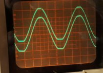
I made new measurements with my single Amnesis prototype (Darlington output stage):
Ups= +-44V
Sine wave 1KHz
Scope 20V/scale
The lower curve is the output signal (minus pole of cap) at clipping point (+-40V)
The upper curve is the voltage at plus pole of the cap connected to the middle of the two 1k resistors (+44V).
As you see the maximum voltage across the cap is below +30V.
The same is valid for the cap of the negative side.
Hi Max,
I made new measurements with my single Amnesis prototype (Darlington output stage):
Ups= +-44V
Sine wave 1KHz
Scope 20V/scale
The lower curve is the output signal (minus pole of cap) at clipping point (+-40V)
The upper curve is the voltage at plus pole of the cap connected to the middle of the two 1k resistors (+44V).
As you see the maximum voltage across the cap is below +30V.
The same is valid for the cap of the negative side.
Attachments
Hi Max,
The layout contains 4 parallel resistors (0.25W) or 1 resistor 1-2W.
Which low tempco units do you prefer (brand). What is the component seize (datasheet), what is the price.
I don't use output relais/protection circuits to separate the speaker from
the amp (no relais in the signal path)
The optional relais in my layout helps effectual to mute 'plops' in the speaker during power up and power down.
There are many relais possible with the correct make/break contact arrangement. I post examples later.
From a layout point of view this can be determined later.
Cheers
Feedback resistors are good from 48K to 50k paralleled. Or 12k-12.5K single. Simulations do not show it but I commented before the work of an audio guru (which name now escapes me) that measures significant THD reduction with parallel or series-parallel (low tempco) equivalent resistors.
The layout contains 4 parallel resistors (0.25W) or 1 resistor 1-2W.
IF you find the amp worthy, then it is recommended that all resistors on the signal path be swapped to high Q, low tempco units.
Which low tempco units do you prefer (brand). What is the component seize (datasheet), what is the price.
Can you give the model/dimensions of the output relays?
I don't use output relais/protection circuits to separate the speaker from
the amp (no relais in the signal path)
The optional relais in my layout helps effectual to mute 'plops' in the speaker during power up and power down.
There are many relais possible with the correct make/break contact arrangement. I post examples later.
You know BJTs on the input CFP could be swapped for equivalent (cbe pinout) with lower Ccb/lower V capability (BC550-560 for instance), as they face very low voltages...
You are the experts.
R27 of the Hagermann Vbe multiplier must be chosen given the behavior of the chosen BJT (T9) for that position, following the paper I posted before.
From a layout point of view this can be determined later.
Cheers
Hi Max,
I made new measurements with my single Amnesis prototype (Darlington output stage):
Ups= +-44V
Sine wave 1KHz
Scope 20V/scale
The lower curve is the output signal (minus pole of cap) at clipping point (+-40V)
The upper curve is the voltage at plus pole of the cap connected to the middle of the two 1k resistors (+44V).
As you see the maximum voltage across the cap is below +30V.
The same is valid for the cap of the negative side.
You beat me to the clock
Attachments
Hi Max,
*The layout contains 4 parallel resistors (0.25W) or 1 resistor 1-2W.
*From a layout point of view this can be determined later.
Exactly.

Which low tempco units do you prefer (brand). What is the component seize (datasheet), what is the price.
I don't remember from memory. We will have to search and it will also depend on how cheap I feel at the time.
(size is standard 0.25W-0.5W)
I don't use output relais/protection circuits to separate the speaker from
the amp (no relais in the signal path)
The optional relais in my layout helps effectual to mute 'plops' in the speaker during power up and power down.
There are many relais possible with the correct make/break contact arrangement. I post examples later.
Cheers
Ah! Yes, now I remember you mentioned this already. So a low power one will do?
Anyway, if it works OK, offset shall be under 20mV, so no pops expected. On the contrary, I recommend speaker protection circuits on all DIY amps...at least on the development/optimization period
Best wishes,
M.
Resistors
Hi Max,
I just want the prevent that the layout has to be changed completely due to
more board space is required for many resistors.
For resistors in audio signal path I used a grid of 10.16mm (400 mil).
For standard resistors 0.25W metal film (e.g. current sources) I used
7.56 mm (300 mil).
For the bootstrap resistors 1K I used 3W types (grid 20.8mm) and for the 2k2 resistors (Driver stage) 2W types (grid 15.2mm) to avoid increasing the PCB length.
Cheers
Hi Max,
low tempco units component seize
I don't remember from memory. We will have to search and it will also depend on how cheap I feel at the time.
(size is standard 0.25W-0.5W)
I just want the prevent that the layout has to be changed completely due to
more board space is required for many resistors.
For resistors in audio signal path I used a grid of 10.16mm (400 mil).
For standard resistors 0.25W metal film (e.g. current sources) I used
7.56 mm (300 mil).
For the bootstrap resistors 1K I used 3W types (grid 20.8mm) and for the 2k2 resistors (Driver stage) 2W types (grid 15.2mm) to avoid increasing the PCB length.
Cheers
Sorry FdW, I don't get it.
Are you referring to the bootstrap caps?
Cheers,
M.
Yep, I was kind of in a hurry
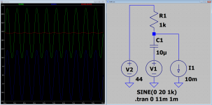
What I wanted to show is, how you could determine a value for the bootstrap capacitor by observing the 'red'-line
A small sim goes a long way (I hope).
Hi Max
I just want the prevent that the layout has to be changed completely due to
more board space is required for many resistors.
For resistors in audio signal path I used a grid of 10.16mm (400 mil).
For standard resistors 0.25W metal film (e.g. current sources) I used
7.56 mm (300 mil).
For the bootstrap resistors 1K I used 3W types (grid 20.8mm) and for the 2k2 resistors (Driver stage) 2W types (grid 15.2mm) to avoid increasing the PCB length.
Cheers
That seems OK.
Besides, legs can be bent.
I bought my quality R years ago. I don't remember where are the "bills". Any one with 50ppm (25ppm if you feel splendid) or less shall be good.
What is the pace for the PS caps' leads, BTW?
Dear FdW wrote:
Yep, I was kind of in a hurry
What I wanted to show is, how you could determine a value for the bootstrap capacitor by observing the 'red'-line
A small sim goes a long way (I hope).
Yes, thanks for your interest and support.
I believe we can be confident on the minimal value we found: 35V standard or more. This can be bypassed also with good film cap.
I repaired my channel with the last configuration. It seems stable with 6R8 dummy load. No time to listening though...family obligations...
BTW, JOSI1, did you listened to your single channel? And, is it stable? Just curious...anyhow, at least 48hrs of burning-in are recommended before critical listening.
Cheers, guys,
M.
Last edited:
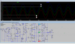
Guys, I revisited my crazy alternate compensation scheme on the Darlington output amp. It behaves well on square wave test and in stability terms, IMHO.
Is there an explicit way to show stability margins in LTspice?
You know I am a nullity with LTspice: I've tried without luck to introduce the BD139/140.
I hope today I will have time to complete my test with the last configuration proposed as optative oscillation killer: 50R-10nF from base to ground of the driver's cascode.
Cheers,
M.
Attachments
Last edited:
- Home
- Amplifiers
- Solid State
- The AMNESIS amp: a good amplifier, like a gentleman, has no memory.