OK. I've been playing around with LTspice a bit. I had to virtually mod the VAS from a bootstrap load into a CCS loaded one to simplify things...adding resistors here and there and BC capacitances and playing around with values made me get further understanding of the problems...with one simulation with PS upgraded to +/-44VDC I got phase at (-)110degrees for 0 gain and (-)180 degrees at -20db of gain. This is good, right?
Anyway, while global loop might get stable, there seem to be also local feedback loops at the output section (OS) that are prone to oscillation, hence my trial and error approach.
Higher supplies apparently improve stability margins...
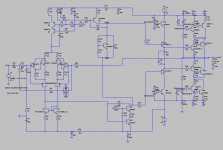
I post a schematic with multiple new Rs and Cs, a couple with values and lots without values: the later are not present in the circuit. I put them there to show how many variants I am testing. PS: I forgot some emitter degenerations...
Anyway, 10R on the emitter of the first element of the cascode (OS) seem to improve things and the amp is stable with multiple program material at loud volumes (peaks of 6W) without detriment to sound.
It's a pity that no guru jumps in and advice this eternal beginner but f***!, I'll do it all by myself
I am fascinated (to use a term that I hate as being sissy) both by cascode and by CFP configurations and I am swimming around multiple EE fora to gain further insight about their intricacies...what I read makes me think that even scholars are puzzled sometimes by them...
Anyway, while global loop might get stable, there seem to be also local feedback loops at the output section (OS) that are prone to oscillation, hence my trial and error approach.
Higher supplies apparently improve stability margins...
I post a schematic with multiple new Rs and Cs, a couple with values and lots without values: the later are not present in the circuit. I put them there to show how many variants I am testing. PS: I forgot some emitter degenerations...
Anyway, 10R on the emitter of the first element of the cascode (OS) seem to improve things and the amp is stable with multiple program material at loud volumes (peaks of 6W) without detriment to sound.
It's a pity that no guru jumps in and advice this eternal beginner but f***!, I'll do it all by myself
I am fascinated (to use a term that I hate as being sissy) both by cascode and by CFP configurations and I am swimming around multiple EE fora to gain further insight about their intricacies...what I read makes me think that even scholars are puzzled sometimes by them...
Attachments
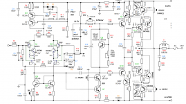
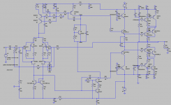
One of the many iterations that I am trying/simulating.
Note that this one has CCS loaded VAS, not bootstrapped...
I don't know if this CCS will sound better or worse than boots...
Note that this one has CCS loaded VAS, not bootstrapped...
I don't know if this CCS will sound better or worse than boots...
Attachments
I forgot to mention that I "borrowed" the spice models from AndryOL's on his "One of the best CFA..." threads...
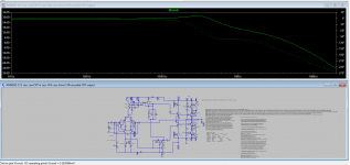
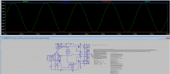
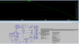
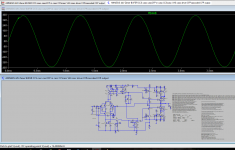
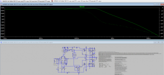
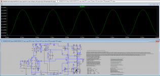
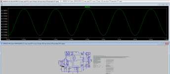
Here a +/-44V supply Amnesis, with 1.5VAC input signal. It had some ringing at the crests that went down with 1uF caps from +/-Vbiascasc nodes to supplies. I will also try this caps to ground...
Tinny curves are from those +/-Vbiascasc nodes.
Offset is 5mV. VAS bias is 26mA. Current for each casc-CFP input tail is 3.3mA.
Attachments
Last edited:
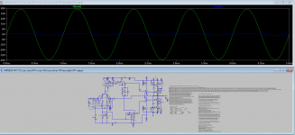
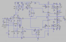
With 6V2 Zeners for the cascode Vbias.
Will check is there is no difference in sound and behavior between R to ground or R to output...
Edit: I had to increase Cdom again to 100p because margins suffered from the above mod.
Will check is there is no difference in sound and behavior between R to ground or R to output...
Edit: I had to increase Cdom again to 100p because margins suffered from the above mod.
Attachments
Last edited:
Appart cascodying the CCS load for the VAS, I always wanted to try this crazy thing: a common-base buffer for the output of the input section.
Everything OK until I reduce the bias; the something strange happens.
I wonder how will it sound...
Everything OK until I reduce the bias; the something strange happens.
I wonder how will it sound...
Attachments
Last edited:
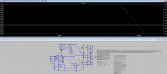
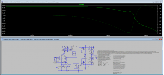
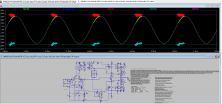
Look, this is the kind of stuff that appears when bias is too high.
Here with +645mV and -595 on the base of the output CFP. VAS current is 46mA. Green is output, red and cian? are +Vbiascasc and -Vbiascasc nodes respectivelly.
With lower bias, things look good.
Here with +645mV and -595 on the base of the output CFP. VAS current is 46mA. Green is output, red and cian? are +Vbiascasc and -Vbiascasc nodes respectivelly.
With lower bias, things look good.
Attachments
Last edited:
Ah! The joy of having a stable circuit!
Doesn't come that often...
Adding C9 -C11 (1uF) to the real 32V amp made it very unstable: just tapping the FB trace induced 0,5V oscillation about 800Kz, SVPT-like waveform...
With just resistors shall be then.
Returning the common-base bias to ground or to output does not seem to alter sound...pity, I was hopping for some magical effect, like Shade.
Cheers,
M.
I always wanted to try this crazy thing: a common-base buffer for the output of the input section.
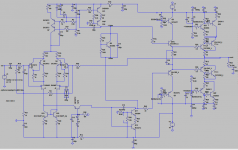
This mod accentuates a ringing that I discovered at the output of the differential amplifier. I reduced one of the R of the CFP from 1k to 600 as this shares better the current for both the BJTs and the ringing disappeared.
BTW, I modded the output section to a, IMHO, more technically correct configuration, with a small degeneration R for the driver of the output CFP and the collector of the driven directly connected to output.
As it is, it makes nice curves.
Attachments
-
 amnesis 600 44V 5R CCS casc CFPcasc in cascVAS cascDrive CFP-cascCFPout schem.png39.4 KB · Views: 378
 -
 amnesis 600 44V 5R CCS casc CFPcasc in cascVAS cascDrive CFP-cascCFPout.png57.1 KB · Views: 364
 -
AMNESIS 600 5R 44V CCS casc cascCFP in casc VAS casc driver CFPcascoded CFP output.asc23.3 KB · Views: 95
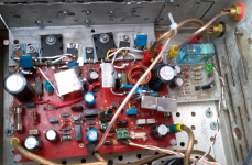
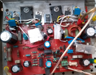
I forgot to post pictures of the actual amp. These are of a previous iteration, sans emitter's R for the cascodying CFP BJTs and with original input filter.
Note my tweak for speaker binding posts.
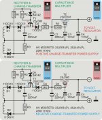
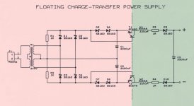
Also, the power supply is a "charge-transfer supply", from -ECdesigns.
I just can't build something without introducing my mods...Aquarius rising
Cheers,
M.
Note my tweak for speaker binding posts.
Also, the power supply is a "charge-transfer supply", from -ECdesigns.
I just can't build something without introducing my mods...Aquarius rising
Cheers,
M.
Attachments
Hi dear,
How sunny is down there in this season?
Here we had 2°Celsius today and I have my Amnesis in the patio where my "shop" is relegated by a superior power, hehe.
My Amnesis is a joy to listen to (when stable) with instant relaxation and musical bliss. I know I put myself between the horses legs with this output configuration but it is worth every effort. I did not found yet this one descibed...maybe I will get the authorship
The charge transfer does improve sound. It still has ground connection in common. I increase values of active and passive elements for a High Power circuit, since the original is for low power.
I'll permit myself to re-post the explanation -EC- posted on his "TDA1541A" thread:
I hope you like it.
Take care and have fun, my friend.
M.
PS: the regulator part T2 is optional...I don't use it.
How sunny is down there in this season?
Here we had 2°Celsius today and I have my Amnesis in the patio where my "shop" is relegated by a superior power, hehe.
My Amnesis is a joy to listen to (when stable) with instant relaxation and musical bliss. I know I put myself between the horses legs with this output configuration but it is worth every effort. I did not found yet this one descibed...maybe I will get the authorship
The charge transfer does improve sound. It still has ground connection in common. I increase values of active and passive elements for a High Power circuit, since the original is for low power.
I'll permit myself to re-post the explanation -EC- posted on his "TDA1541A" thread:
> First the primary smoothing cap (Cp) is charged with the polluted rectified voltage through D1 ... D3. R1 puts a positive voltage on P-FET T1, switching it OFF, and disconnecting the load during this charge cycle.
All interference surges through the primary smoothing cap -not the connected load- The severety of the pollution really doesn't matter at this point, main purpose is to get the primary smoothing cap Cp charged.
> Next the rectified voltage drops below the voltage across the smoothing cap Cp plus voltage drop across the rectifier diodes D1 & D3 or D2 & D3, now the rectifier diode no longer conducts, and interrupts the noisy charge current. All that remains after this interference attack is a charged capacitor. The P-MOSFET is not yet switched-on as -Vgs is still too low to make it conduct.
Now we have a floating charged cap (Cp), it's basically similar to a battery connected to GND with the minus terminal. Needless to say that all the interference signals during charging are not "remembered" by capacitor Cp.
> As the sinewave voltage drops, P-channel MOSFET -Vgs gets high enough, and T1 switches-ON. T1 now connects charged cap Cp to both Cs and load, the charge of the primary smoothing cap supplies clean energy to both Cs and load.
> After the sinewave voltage rises again, -Vgs drops and T1 is switched OFF. Now the secondary smoothing cap Cs continues to supply clean electrical energy to the load.
The cycle is repeated 50/60 times a second with half-wave rectifiers, and 100/120 times a second with full-wave rectifiers.
Both D4 and D5 (Zener diode and Schottky diode) are added for protecting the gate of T1.
D3 was added to create the required switching signal for T1. T1 is switched-on by pulling the gate to GND through both R1 and R2, the protection diodes D4 and D5 will limit -Vgs. T1 is switched off by pulling the gate to plus through R1.
The peak charge transfer current through Cs is limited by the P-MOSFET RdsON, but can be further manipulated by adding an extra series resistor in the drain lead.
I hope you like it.
Take care and have fun, my friend.
M.
PS: the regulator part T2 is optional...I don't use it.
Attachments
Last edited:
Hi Max!
I am watching your efforts with the interest,
but the power supply for dac is interesting too, please provide a link to 1541 thread,
thank you in advance!
OK. Thank you.
So we are two interested people in this revolutionary amp
. 
http://www.diyaudio.com/forums/digi...e-nos-dac-using-tda1541a-244.html#post5434521
John just posted a novel DAC with simultaneous mode input configuration. A great contribution to DIY, since he is also commited to his great Mosaic DAC invention.
Search for "charge transfer supply" in the above configuration and in "floating" configuration, which doubles output V. I usually put some good quality ferrites in the ground leads of DACs.
My main system n°1 and n°2 are connected to balanced power.
Cheers,
M.
Attachments
Last edited:
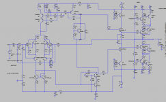
This one is good. I tried until 590mV/-560mv bias from base to ground of output elements.
It is very enlighting to see the wave forms on the cascodying CFPs...maybe over-damped.
I have also cascoded VAS and CCS which I will try to convert to Hawksford...
It is very enlighting to see the wave forms on the cascodying CFPs...maybe over-damped.
I have also cascoded VAS and CCS which I will try to convert to Hawksford...
Attachments
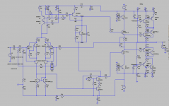
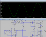
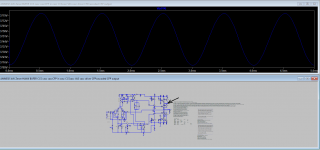
Revisiting the diff out buffer idea with, what I suppose to be, Hawksford Cascoded VAS, produced no oscillation of the diff output, though slight distortion may be seen. In -ECdesigns-' diffamp harmonic distortion can be reduced with trimmer pot in degeneration resistors for the emmiter input pair...
I reached the best sine for the output node of the cascodyingCFP. The black arrows shows the tester point. I may have something here...
I was looking for oscillation to test Bimo's idea of stopper R in gates of the input JFETs (cascodying)...
PS: bias may be too high. Increase R24 to 1K1.
I reached the best sine for the output node of the cascodyingCFP. The black arrows shows the tester point. I may have something here...
I was looking for oscillation to test Bimo's idea of stopper R in gates of the input JFETs (cascodying)...
PS: bias may be too high. Increase R24 to 1K1.
Attachments
-
 amnesis 44V Zener 1u HAWK BUFFER in CASC NODE.png47.5 KB · Views: 193
 -
 amnesis 44V Zener 1u HAWK BUFFER in neg CASC.png76.9 KB · Views: 138
 -
AMNESIS 44V Zener HAWK BUFER CCS casc cascCFP in casc CCScasc VAS casc driver CFPcascoded CFP ou.asc24.4 KB · Views: 70
-
 amnesis 44V Zener 1u HAWK BUFFER DIF OUT.png69.8 KB · Views: 127
Last edited:
Hi.
Lots of new insight since I learned the FTT function from LTspice (BTW LTspice freezes 9/10 times and it is a pain to use...or maybe the PC is to blame) and by reading newly found articles by "Le Feu Seigneur de Lavardin, Hephaïstos", one of my heroes The guy, which was a French EE (BTW, mchambin) and more intelligent than I am, used a cascode INSIDE the output Siklay pair in one of his amps, while I use it OUTSIDE the CFP. Very clever indeed. I suppose that would make the amp more stable or less temperamental. He cascoded only the driver BJT but you know me by now, I will also cascode the complementary BJT (CFP inside CFP), somehow...I will find the way.
L'étage de sortie de l'ampli -1- réflexions théoriques (Héphaïtos)
I now feel that the CFP, while driven as an emitter follower, behaves more like a common-emitter, soundwise and from a (un)stability PoV... and, the pre-drivers probably must be connected to the output also...
Wish me luck.
M.
Lots of new insight since I learned the FTT function from LTspice (BTW LTspice freezes 9/10 times and it is a pain to use...or maybe the PC is to blame) and by reading newly found articles by "Le Feu Seigneur de Lavardin, Hephaïstos", one of my heroes
The guy, which was a French EE (BTW, mchambin) and more intelligent than I am, used a cascode INSIDE the output Siklay pair in one of his amps, while I use it OUTSIDE the CFP. Very clever indeed. I suppose that would make the amp more stable or less temperamental. He cascoded only the driver BJT but you know me by now, I will also cascode the complementary BJT (CFP inside CFP), somehow...I will find the way.L'étage de sortie de l'ampli -1- réflexions théoriques (Héphaïtos)
I now feel that the CFP, while driven as an emitter follower, behaves more like a common-emitter, soundwise and from a (un)stability PoV...
and, the pre-drivers probably must be connected to the output also...Wish me luck.
M.
- Home
- Amplifiers
- Solid State
- The AMNESIS amp: a good amplifier, like a gentleman, has no memory.