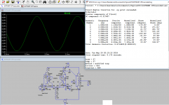
Bias was too high. With R24 at 1150Rand with one extra diode to bias the cascodes, IF I understood correctly, phase margin is 60° and power margin is at -18dB.
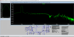
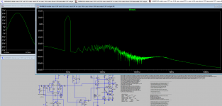
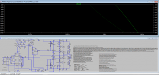
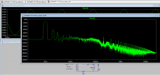
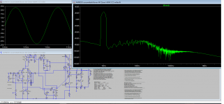
The FTTout is funny, with even order harmonics plunging beneath the noise floor
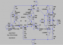
Vbe multiplier gives asimetric biasing I have to try now Hagermann's circuit.
The FTTout is funny, with even order harmonics plunging beneath the noise floor
Vbe multiplier gives asimetric biasing
I have to try now Hagermann's circuit.Attachments
With 48V supplies.
Where did the harmonics go?
Guys, I need help to lower the bias. I am not good at that.
Where did the harmonics go?
Guys, I need help to lower the bias. I am not good at that.
Attachments
The last one needed double bias for the cascode. I'll update later.
Following my crazy obsession with overly complicated outputs and with "improved" bias:
Anyway, I'll probably try VFET cascodying simple emitter follower, á la Sansui/sony...autobias.
Following my crazy obsession with overly complicated outputs and with "improved" bias:
Anyway, I'll probably try VFET cascodying simple emitter follower, á la Sansui/sony...autobias.
Attachments
Disclaimer: I'm a novice exploring really complex stuff so all my statements must be taken with a grain of salt, as sometimes two mistakes can cancel each other.
Confessions:
1) my first cascoded emitter follower output (VSSA; a CFA) wired in conventional wisdom showed, I swear, early clipping. That is why all my EF cascode Vbias (Blame and Amnesis) are 26V or higher. Revisiting the idea, after reading Hephaïstos paper proved me wrong, so I changed back the Vbias for the drivers to 2,1 to 2,7V (to ground) and the thing works on paper and in real life.
2) Tired from oscillation of complex output configurations I went back to the simple cascoded EF output, to listen to a stable amp (one of the channels still has clusters of oscillation with highish volume but remains composed) and to convince me that there is no difference in sound: well there is...simple cascoded EF sounds uninvolving compared to previous tries.
In a perfect world, with stable amp, my preferences would be: EF--> cascoded EF--> cascoded-CFP--> CFP with a CFP cascode of some sort.
See that I am only playing with outputs and not with thermal memory here, as I desperately need an OS that can cope with low TMD. As I said, I'll probably try cascode with VFET or with depletion mode Mosfet (if I find suitable ones) that shall auto-bias themselves, connected to output (ground).
I shall post later schematics and simulations of a simple EF amp for those that wish to build the simplest version and have a taste of how low TMD can or cannot sound.
Magic: does magic exist? While making my dozens of simulations with many variations I went back from double cascoded CFP (cascode inside the CFP) to cascoded-EF but been lazy, l did not erase the resistor-diode string parallel to output that served to bias the common emitter part of the cascode. It shouldn't matter, right? Well, given certain combinations of currents and R, the innocent parallel R-D-R-D string apparently did matter as it changed the harmonic content quite a bit for the better. I have no clue as why this is...
It has occurred to me that simulations and reality behave differently. I shall talk about this later. So I wired in the real amp the R-D string just to be sure... I makes a difference. Agreed, I am crazy after so many experiments, so I will connect a switch to be !00% sure that it is not my imagination.
Now, the cascoded-EF output does sound quite involving. Though the bursts of oscillations persist on one channel. I will go back to EF-VAS, cacoded as a little bird (ein kleiner Woglein) adviced me.
Can we connect a speaker model instead of a 8Ohm R to the output?
Can we model back-EMF in simulation?
Who knows good depletion mode Mosfets (N and P) to try?
Simulations and schematics to follow.
Thanks you very much.
M.
Confessions:
1) my first cascoded emitter follower output (VSSA; a CFA) wired in conventional wisdom showed, I swear, early clipping. That is why all my EF cascode Vbias (Blame and Amnesis) are 26V or higher. Revisiting the idea, after reading Hephaïstos paper proved me wrong, so I changed back the Vbias for the drivers to 2,1 to 2,7V (to ground) and the thing works on paper and in real life.
2) Tired from oscillation of complex output configurations I went back to the simple cascoded EF output, to listen to a stable amp (one of the channels still has clusters of oscillation with highish volume but remains composed) and to convince me that there is no difference in sound: well there is...simple cascoded EF sounds uninvolving compared to previous tries.
In a perfect world, with stable amp, my preferences would be: EF--> cascoded EF--> cascoded-CFP--> CFP with a CFP cascode of some sort.
See that I am only playing with outputs and not with thermal memory here, as I desperately need an OS that can cope with low TMD. As I said, I'll probably try cascode with VFET or with depletion mode Mosfet (if I find suitable ones) that shall auto-bias themselves, connected to output (ground).
I shall post later schematics and simulations of a simple EF amp for those that wish to build the simplest version and have a taste of how low TMD can or cannot sound.
Magic: does magic exist? While making my dozens of simulations with many variations I went back from double cascoded CFP (cascode inside the CFP) to cascoded-EF but been lazy, l did not erase the resistor-diode string parallel to output that served to bias the common emitter part of the cascode. It shouldn't matter, right? Well, given certain combinations of currents and R, the innocent parallel R-D-R-D string apparently did matter as it changed the harmonic content quite a bit for the better. I have no clue as why this is...
It has occurred to me that simulations and reality behave differently. I shall talk about this later. So I wired in the real amp the R-D string just to be sure...
I makes a difference. Agreed, I am crazy after so many experiments, so I will connect a switch to be !00% sure that it is not my imagination.Now, the cascoded-EF output does sound quite involving. Though the bursts of oscillations persist on one channel. I will go back to EF-VAS, cacoded as a little bird (ein kleiner Woglein) adviced me.
Can we connect a speaker model instead of a 8Ohm R to the output?
Can we model back-EMF in simulation?
Who knows good depletion mode Mosfets (N and P) to try?
Simulations and schematics to follow.
Thanks you very much.
M.
Sorry. PC is too slow. LTspice freezes or takes ages.
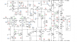
I added a Amnesis/Blame with simple EF output for those interested. Went back to EF-VAS on the schematics but resistances and voltages must be checked prior to connect the output devices. I have connectors for this purposes on board.
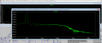
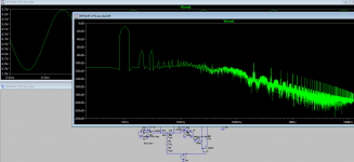
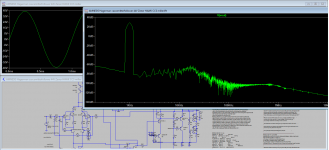
I added some plots of how the responses should look for the cascoded-EF. The // R-D-R-D string passes a couple of mA... very cheap trick: worth a try.
The differences with the real amp: 32 vs 44V supplies; 1uF capacitor // to biasing R on output cascode makes things worse so it is not connected on board; biasing diode string for the drivers cascode is connected to output. All other connection make oscillation worse in one channel; I did not yet use EF-VAS.
Cheers.
M
I added a Amnesis/Blame with simple EF output for those interested. Went back to EF-VAS on the schematics but resistances and voltages must be checked prior to connect the output devices. I have connectors for this purposes on board.
I added some plots of how the responses should look for the cascoded-EF. The // R-D-R-D string passes a couple of mA... very cheap trick: worth a try.
The differences with the real amp: 32 vs 44V supplies; 1uF capacitor // to biasing R on output cascode makes things worse so it is not connected on board; biasing diode string for the drivers cascode is connected to output. All other connection make oscillation worse in one channel; I did not yet use EF-VAS.
Cheers.
M
Attachments
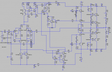
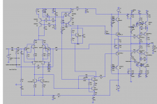
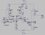
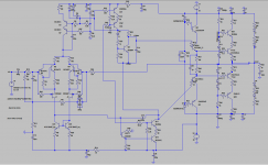
The PC can handle smaller circuits so, passing to another topic, I post the Diffamp, which can be good as input for power amp (headamp; preamp) or as output for a balance output DAC.
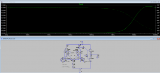
See plots of the original diffamp and of the modified cascoded compound-CFP. I used some JFET available on the library...
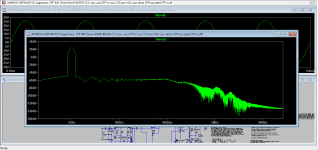
Look how when both branches of the CFP share equal current (1K2 and 2K for 17V supplies) the noise floor goes down. Next, experiments with R on collector and higher PS, active CCS and loads, and cascodying the buffers...
I hope you like it.
M.
See plots of the original diffamp and of the modified cascoded compound-CFP. I used some JFET available on the library...
Look how when both branches of the CFP share equal current (1K2 and 2K for 17V supplies) the noise floor goes down. Next, experiments with R on collector and higher PS, active CCS and loads, and cascodying the buffers...
I hope you like it.
M.
Attachments
BC5550 NPN driving VAS should be PNP with 39k resistor to ground driving VAS off emitter.
Oops! That was a typo: 2N5550/5551 NPN should be.
But you are right. There were several recommendations to avoid destruction. I'll check my schematics.
Thank you very much.
M.
I post the Diffamp, which can be good as input for power amp (headamp; preamp) or as output for a balance output DAC.
I hope you like it.
M.
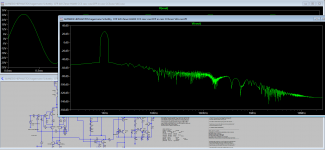
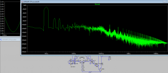
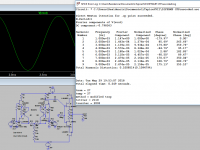
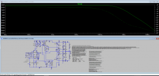
I learned how to evaluate THD with the .four 1kHz V(Vout) directive.
for this simple diffamp, THD is 0.87% (mainly 2nd and 3rd H) and now with cascoded outputs THD 0.1% ...strange, FFT seamed worse...
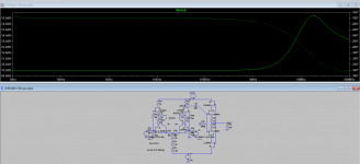
And lastly Bode comparison for cascoded out v/s simple common-drain out. Can it oscillate at UHF?Cheers,
M.
Attachments
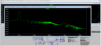
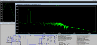
Look at the noise floor of this 17V version.
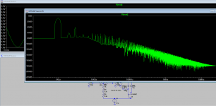
I dare you to compare the circuit with and without the R-D-R-D string in parallel with the output and tell me it does no influence response...you can play with the values of R a bit.
Then connect, just for fun, the midpoint of this RDRD string to the midpoint of the cascode out...
I dare you to compare the circuit with and without the R-D-R-D string in parallel with the output and tell me it does no influence response...you can play with the values of R a bit.
Then connect, just for fun, the midpoint of this RDRD string to the midpoint of the cascode out...
Attachments
Last edited:
Remember one channel had bursts of oscillation on power peaks???
Fortunatelly I remembered that Dr. Leach on his Low TIM amp and Uncle Charlie on his Blame ES, recommended connecting the RC from output to ground (R45 15 Ohm; C21 100nF; from .asc file) part of the Zobel outside the board; for practical reasons, on the speakers' binding posts. The reason being that due to packed layout that subcircuit can introduce positive feedback that can exite the input through signal ground. Well, now that channel is behaving correctly and just passed the afternoon listening to some good music and abusing a little the speakers. I think I will also mod my Sony TA-VFET amp this way.
Increasing damper R to the bases of the EF outputs from 2R2 to 12R2 made oscillation worse...
Remember the 1uF cap that decouples the base of the cascodying T for the outputs? Connecting one of them to the oscillating amp produced the biggest instantaneous explosion of the cascodying BJTs for the drivers! The rest of the BJTs survived. That was when I reduced the biasing for the cascodying elements of the driver section to 3,6V because LT spice whowed nice curves...I went back to +/-26V but I could investigate lower V.
My Amnesis with cascoded EF output seem to be stable so far and shows the desired transparency, timbral accuracy and discrimination, together with dynamic contrasts that warrant further critical audition on the bigger systems.
Cheers,
M.
Last edited:
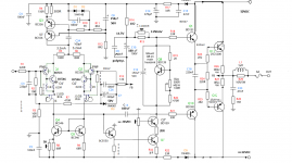
Amnesis with power LED biasing the common-base BJT from the cascoded drivers to +/-41VDC and with 1.5V input signal gives +/-40V (80Vppk) clean output with 0.0034%THD.
Higher supplies give somewhat lower THD. This one had 48V on the front-end and 44V on the output section, just in case I decide independent regulated supplies.
It is safe to decouple that biasing nodes (labelled +/-Vbiascasc on .asc) with a film cap. No explosion.
Higher supplies give somewhat lower THD. This one had 48V on the front-end and 44V on the output section, just in case I decide independent regulated supplies.
It is safe to decouple that biasing nodes (labelled +/-Vbiascasc on .asc) with a film cap. No explosion.
Attachments
Last edited:
- Home
- Amplifiers
- Solid State
- The AMNESIS amp: a good amplifier, like a gentleman, has no memory.