Hi and thanks for the interest!
First, I would argue that the MOSFETs are indeed bootstraped in the sense and definition from Dr. Kolinumi (sorry if I miss-spelled) in which the gate is tied to "ground" but also receives a sample of the signal...
I confess, some times I put there on the LTspice schema a gate stopper that is the lowest value that affords good looking Square wave test...
 while then I use some higher R, around 100R, which then would be increased to higher values if I smell oscillation. My scope is kaput and I rely on bias current stability afforded by the addapted Hageman Vbe multiplier, which is very, very stable indeed, to discard oscillation. Sorry, it is the best I can do for now and I know it is not a good technical advice...
  that is why, months ago I offered free PCBs (with anotated errors ) only to experienced and tough DIYers with good testing equipment, to confirm that I am totally-totally nuts! Sadly no-one accepted the challenge...and you don't know what you are missing, hehe.
I profit to comment that a second unit (amp3) has now Peufeu's innovative EF+Darlington resistor arrangement, this time 39R for the base-emitter Rs (Darlington) and 75R for the base-to-base (EF) resistor, which passes much more current. Remember to re-tune for desired current bias after this mod. At my low current (50mA) bias, listening findings are opposite to the expected simulated slightly increased high order harmonics...of course at higher bias, say 120mA, those high order harmonics will be irrelevant...
Cheers,
M.
First, I would argue that the MOSFETs are indeed bootstraped in the sense and definition from Dr. Kolinumi (sorry if I miss-spelled) in which the gate is tied to "ground" but also receives a sample of the signal...
I confess, some times I put there on the LTspice schema a gate stopper that is the lowest value that affords good looking Square wave test...
while then I use some higher R, around 100R, which then would be increased to higher values if I smell oscillation. My scope is kaput and I rely on bias current stability afforded by the addapted Hageman Vbe multiplier, which is very, very stable indeed, to discard oscillation. Sorry, it is the best I can do for now and I know it is not a good technical advice... that is why, months ago I offered free PCBs (with anotated errors ) only to experienced and tough DIYers with good testing equipment, to confirm that I am totally-totally nuts! Sadly no-one accepted the challenge...and you don't know what you are missing, hehe.I profit to comment that a second unit (amp3) has now Peufeu's innovative EF+Darlington resistor arrangement, this time 39R for the base-emitter Rs (Darlington) and 75R for the base-to-base (EF) resistor, which passes much more current. Remember to re-tune for desired current bias after this mod. At my low current (50mA) bias, listening findings are opposite to the expected simulated slightly increased high order harmonics...of course at higher bias, say 120mA, those high order harmonics will be irrelevant...
Cheers,
M.
...First, I would argue that the MOSFETs are indeed bootstraped in the sense and definition from Dr. Kolinumi (sorry if I miss-spelled) in which the gate is tied to "ground" but also receives a sample of the signal...
Yes, I can see that. By "bootstrapped" I meant the ability for the gate to go higher in voltage than the positive voltage rail.
In the way you now have the gate circuit, the gate is 8.2v higher the the output voltage until Vrail-8.2v. As the output goes higher than Vrail-8.2v the MOSFET becomes more and more resistive until it becomes an open circuit around Vrail-Vth.
Was this an intentional choice? What do you gain? Perhaps stability near the rails when capacitances of the MOSFETs become highly non-linear?
The other interesting aspect of this bootstrap arrangement is headroom. How close to the positive rail can the output go before clipping?
...that is why, months ago I offered free PCBs (with anotated errors
I'm not sure about tough, etc., but if I ever buy a 200MHz scope I may ask about the PCBs.

Yes, thank you.
We had VAS, driver and output "cap-bootstrapped" earlier in the QUAD version which sounded very "tubey" but we later found that using that arrangement, as it was, with electrolytics, obscured something in the midrange. We finally settled for no cap which is clear and clean but less impressive in the bass/midbass, and I rested on the idea that the gate needs very tinny current anyway to work in this common-gate config.
In this present configuration the Amnesis is sounding way cleaner and clearer than before so, I am prepared to re-evaluate this "cap-bootstrapped" output, which should be easy to implement.
So, just when you think "I'm done" new experiments appear! Isn't this the best hobby???
About, building: one can always put a big gate-stopper R...
Thanks again for your interest and stimulation,
M.
PS: by tough I mean resilient/impervious to frustration...
We had VAS, driver and output "cap-bootstrapped" earlier in the QUAD version which sounded very "tubey" but we later found that using that arrangement, as it was, with electrolytics, obscured something in the midrange. We finally settled for no cap which is clear and clean but less impressive in the bass/midbass, and I rested on the idea that the gate needs very tinny current anyway to work in this common-gate config.
In this present configuration the Amnesis is sounding way cleaner and clearer than before so, I am prepared to re-evaluate this "cap-bootstrapped" output, which should be easy to implement.
So, just when you think "I'm done" new experiments appear!
Isn't this the best hobby???About, building: one can always put a big gate-stopper R...
Thanks again for your interest and stimulation,
M.
PS: by tough I mean resilient/impervious to frustration...
Last edited:
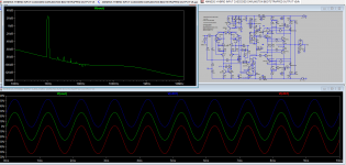
Here, a 5.2 output version with cap-bootstrapped MOSFETs at 118mA bias current, showing lowish THD (for those interested in that) and the magical effect of the bootstrap up-lifting the signal over the rails. Indeed, the roof is lifted (without the limiters) but it clips assymetrically; +40 and -37...
Edit: the series caps parallel to feed-back resistor can be increased gradually until 20p each for a small increase in stability margin (if I understand it correctly) but it gets peaky...
The truth is that I ran out of 20p so I am using 5p for the last amps...
Now I cannot wait to try it, hehe...
Edit: the series caps parallel to feed-back resistor can be increased gradually until 20p each for a small increase in stability margin (if I understand it correctly) but it gets peaky...
The truth is that I ran out of 20p so I am using 5p for the last amps...
Now I cannot wait to try it, hehe...
Attachments
Last edited:
Update:
I have been auditioning the later mods in several systems. To date I have 4/5 amps with the "cap-bootstrapped" drivers and 3/5 amps with the EF+Darlington resistor configuration (Peufeu keeps helping me, without knowing...) for the outputs. Findings are consistent and additive. Both mods let the Amnesis sound to express to a greater degree: attacks; micro-macrodynamics; curves and decays...etc. But what strikes me the most is that color, color density and temperature (to use a visual parallel) increased significantly, so much so that, for example Amp 3 now betters Amnesis VFET, which was always the best performer by far, in that respect and even in coherence of the musical presentation of individual instruments and between instruments. It is difficult to explain this last point; it must be heard...it sounds alike class A with class AB outputs...
I recently upgraded the VFET amp to "cap-bootstrapped" drivers and began the audition: I now understand that the previous configuration was a big mistake; it was just that I was sooo glad that it even worked that I decided to stop there and rest for a while...
The fift amp will remain as a "QUAD" and I will probably build a new amp with Sziklai output in the future, using my pro-PCBs.
Amp1 still has the necessary to just add caps for a genuine bootstrapping of the MOSFETs, but I am worried for the monster bass that I will achieve in advance...
Cheers,
M.
Still dancing in the Field of Unlimited Potential...
Attachments
Last edited:
OK. After a small rest, playing with my Otari tape machine, I had the time to upgrade my Amp1 to the previously tested "cap-bootstrapped" outputs. I chose Amp1 because, as you may recall, I described its sound as liquid, detailed but rather lean, wanting in terms of bass/midbass, and because of the fact that it still has the split resistor required for that mod from the former QUAD bootstrapped configuration, making the mod easy. This time I installed toggle switches to AB the mod. After I checked that liquidity and detail were not greatly compromised, I continue with extended auditions. The change is worst than anticipated in the sense that bass/midbass are greatly increased, both in extension and power, with a sense of increased punch/dynamics and body of instruments, as experimented before (QUAD) but benefited with the present Cap-Bootstrapped Darlington Drivers which affords openness, layering and detail. I will let the unit burn in until my final veredict, because some digital recordings may sound odd in the midrange. Perhaps I will add later film caps// to the Elcaps...the 35W little amp now sounds like a 350W big amp...I could add this feature to the next PCB with a jumper to select or deactivate the cap-bootstrap at will...
On another topic, given that I live in audiophile isolation here, I greatly appreciated the visit to a friend's place profitting from his Dad visiting him. The gentleman has extensive experience in Hi-End circles of the capital city of Santiago. We auditioned only vynil through a good direct drive turn-table, a Rotel amp, used later as preamp to my power amps, and German Saba acoustic suspension speakers from the 70's. Sorry, he forgot to send me the names of the units to be more specific. The Rotel audition is not worth to mention...we tried first my First One power amp from Lazy Cat with upgraded Hypex SMPS and then my Amnesis VFET amp, with mainly electronic music, Progressive Rock from the 70's and that "Take Five" album whose name now I forgot. Both were very impressed with both my amps, but guess which one was the winner...
We recorded small video clips but the phone's mic could not cope with the task, again. I will try to study how to upload with a competent mic.
Cheers,
M.
in the sense that bass/midbass are greatly increased, both in extension and power, with a sense of increased punch/dynamics and body of instruments, as experimented before (QUAD) but benefited with the present Cap-Bootstrapped Darlington Drivers which affords openness, layering and detail. I will let the unit burn in until my final veredict, because some digital recordings may sound odd in the midrange. Perhaps I will add later film caps// to the Elcaps...the 35W little amp now sounds like a 350W big amp...I could add this feature to the next PCB with a jumper to select or deactivate the cap-bootstrap at will...On another topic, given that I live in audiophile isolation here, I greatly appreciated the visit to a friend's place profitting from his Dad visiting him. The gentleman has extensive experience in Hi-End circles of the capital city of Santiago. We auditioned only vynil through a good direct drive turn-table, a Rotel amp, used later as preamp to my power amps, and German Saba acoustic suspension speakers from the 70's. Sorry, he forgot to send me the names of the units to be more specific. The Rotel audition is not worth to mention...we tried first my First One power amp from Lazy Cat with upgraded Hypex SMPS and then my Amnesis VFET amp, with mainly electronic music, Progressive Rock from the 70's and that "Take Five" album whose name now I forgot. Both were very impressed with both my amps, but guess which one was the winner...
We recorded small video clips but the phone's mic could not cope with the task, again. I will try to study how to upload with a competent mic.
Cheers,
M.
Attachments
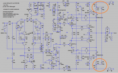
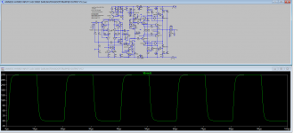
M,If one has some apprehension about Mosfets oscillations, one can always try the Sizklai version.
Cheers,
M.
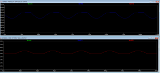
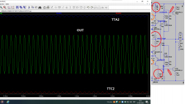
If its not too much to ask, would you please run this version in sim at freq. 20KHz and plot the currents of output bases (that is TTA2 and TTC2 in your schematic).
Thanks a lot!
Your wishes are orders to me... 
Base currents apear to be 333 and 338uA, resp.
We are here to learn and expand the borders of reality, hehe.
All advices accepted.
Cheers,
M.
Base currents apear to be 333 and 338uA, resp.
We are here to learn and expand the borders of reality, hehe.
All advices accepted.
Cheers,
M.
Attachments
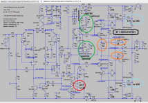
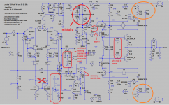
It is a bad idea to use a bootstrap R3R17C18 for a quality amplifier, because through the capacitor from the output of the amplifier to the input of the output stage, additional distortions are added, talking about sound detailing with such an implementation is tantamount to a dreamer, in fact, none of this will happen.This time I installed toggle switches to AB the mod. After I checked that liquidity and detail were not greatly compromised, I continue with extended auditions. The change is worst than anticipated
Attachments
Hehe, I love you too.It is a bad idea to use a bootstrap R3R17C18 for a quality amplifier, because through the capacitor from the output of the amplifier to the input of the output stage, additional distortions are added, talking about sound detailing with such an implementation is tantamount to a dreamer, in fact, none of this will happen.
Edit: I noticed you added comments to the schematics...I will study them,
Thnx.
Edit2: Dear Hennady, the CCS-VAS was compared to the bootstrapped VAS long ago and we decided bootstrapped sounded better, more natural while CCS sounded dry and clinical...but the CCS option can be added at will. Also, the AMpslab C200 Sziklai with LTMD posted above does have a CCS-VAS, which sounds good.
Last edited:
Good luck! and remember you can experiment on a LTMD input section.Interesting results M, no spikes at 20KHz. I am also working on a new CFP design. 😊
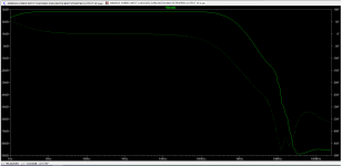
C18 480p from base to collector of the bootstrapped positive driver arrangement causes a slight deformation of the curves. That C is added as recommendation to avoid oscillation and can be lower, around 220p. If you guys know another way to stabilize the output CFP please comment.
Thnx.
M.
This output stage has less distortion. This is a hybrid mix of Emitter follower (EF2) + Darlington. It has the same current gain as the darlington, but it performs a lot better because the drivers remain in class A."Why make it worse?"
Peufeu measured three variants of the output stage (https://www.diyaudio.com/community/...surements-shootout.374367/page-4#post-6719840). Pay attention to the base currents (on the right in the graph) at various connections. The conclusion is obvious.
1. Darlington:


2. Emitter follower (EF2):


3. EF2+Darlington:


Last edited:
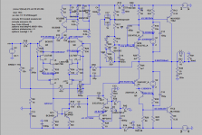
Apart from the bootstrap issue you explained, could you please explain the other points you marked in the schematic? I believe this might be interesting.It is a bad idea to use a bootstrap R3R17C18 for a quality amplifier, because through the capacitor from the output of the amplifier to the input of the output stage, additional distortions are added, talking about sound detailing with such an implementation is tantamount to a dreamer, in fact, none of this will happen.
Peufeu measured three variants of the output stage (https://www.diyaudio.com/community/...surements-shootout.374367/page-4#post-6719840). Pay attention to the base currents (on the right in the graph) at various connections. The conclusion is obvious.
I saw this first of all, that at the moment of switching the output pair of transistors, 47 ohm resistors provide an additional current channel for additional load on the driver stage, i.e. The driver starts to work in class super A only with a large initial current at the moment of switching. It remains only to find out whether the voltage amplifier has enough current, and how much the current control of the bases of the driver stage is carried out. I didn’t model the circuit - I can only guess at the values of currents and voltages at operating points, but judging by the numerous stuffing of the circuit with necessary and unnecessary boosttraps, there are doubts about the quality of the voltage / current converter for this implementation. but I could be wrong...
Last edited:
accelerating link С11R45С27 implemented on the diagram of the second order, but in order to cover the entire correction range, and with Miller correction it is very wide, you need a slope of 6 dB per octave, and this is the first order, it’s hard for me to imagine what will happen to the transient response on a real load with a significant capacitive character , so this leads to a change in the phase angle and reduces the stability of the circuit, 2nd order Miller correction rarely has a large margin of stability, plus the R46 also relies on the amplifier output where the voltage is modulated for the boosttrap ...Apart from the bootstrap issue you explained, could you please explain the other points you marked in the schematic? I believe this might be interesting.
There will be time, I will try to model this "abracadabra", there is a lot of "freak" in it, as it seems to me at first glance...
Hi guys and thanks for your efforts.
Dear Nemool; indeed I have praised Peufeu's work extensivelly but I named the configuration EF+Darlington instead of EF2+Darlington.
Dear Lee and Hennady; about boostraped VAS, I fully understand and have commented before about the influence (distortion, or better, coloration) of the caps in perceived sound, but given that it sounds more natural and dinamic than CCS-VAS so I took the decision to accpet the compromise and tried several combination to reduce the effect. I always use a good quality Elcap//a good quality Film like Wima MKS4 1uF, but the best result are obtained when //also polystyrene 250-275nF (Russian military surplus) which are big. I posted above a picture of them. I also tried a big Vishay 15uF film cap alone for the VFET amp which sounded very clean and soft, but I ended adding the Rubycon ZL + the Polystyrene small cap which is the present configuration. In other positions, I evaluate depending on results. Fortunatelly, MKS1 and MKS2 1uF have 5mm apart legs, so I could reduce the real state needed. So, in that respect, I adhere to the introductory post for the thread: this is not a thread about THD (amplitude response) but about putative effect of LTMD and the goal is satisfactopry reproduction of complex music, not impeccable technical (but soul-less) design...which ampounts to saying: I don't like Dogma...
Cheers,
M.
PS: why bootstrap VAS is perceived as more satisfying than CCS-VAS?? Maybe it is due to the fact that resistors do not "slew"...
Dear Nemool; indeed I have praised Peufeu's work extensivelly but I named the configuration EF+Darlington instead of EF2+Darlington.
Dear Lee and Hennady; about boostraped VAS, I fully understand and have commented before about the influence (distortion, or better, coloration) of the caps in perceived sound, but given that it sounds more natural and dinamic than CCS-VAS so I took the decision to accpet the compromise and tried several combination to reduce the effect. I always use a good quality Elcap//a good quality Film like Wima MKS4 1uF, but the best result are obtained when //also polystyrene 250-275nF (Russian military surplus) which are big. I posted above a picture of them. I also tried a big Vishay 15uF film cap alone for the VFET amp which sounded very clean and soft, but I ended adding the Rubycon ZL + the Polystyrene small cap which is the present configuration. In other positions, I evaluate depending on results. Fortunatelly, MKS1 and MKS2 1uF have 5mm apart legs, so I could reduce the real state needed. So, in that respect, I adhere to the introductory post for the thread: this is not a thread about THD (amplitude response) but about putative effect of LTMD and the goal is satisfactopry reproduction of complex music, not impeccable technical (but soul-less) design...which ampounts to saying: I don't like Dogma...
Yes, we will take some time to understand and or try options...Apart from the bootstrap issue you explained, could you please explain the other points you marked in the schematic? I believe this might be interesting.
Dear Hennady, do you mean the simulation does not work?The scheme is not working - it is not clear what to discuss here ..
Cheers,
M.
PS: why bootstrap VAS is perceived as more satisfying than CCS-VAS?? Maybe it is due to the fact that resistors do not "slew"...
Yes, it is so. I modeled the circuit - the model does not go into operating mode ...Dear Hennady, do you mean the simulation does not work?
Where can I see a practical version of the scheme?
- Home
- Amplifiers
- Solid State
- The AMNESIS amp: a good amplifier, like a gentleman, has no memory.