Hello,
I'm modifying an old power amp, which has a very sophisticated speaker protection circuitry To make things easy with my modifications, I would like to place a relay at the amplifier output.
Now, I have found a pair of S202S01 SSRs among my parts and I'm wondering if it would be reasonable to use these
Does anyone have experience with SSRs as speaker on/off switch?
Or do you see any problems using these (apart from heat dissipation)?
Best gegards,
Frank
I'm modifying an old power amp, which has a very sophisticated speaker protection circuitry
To make things easy with my modifications, I would like to place a relay at the amplifier output.Now, I have found a pair of S202S01 SSRs among my parts and I'm wondering if it would be reasonable to use these
Does anyone have experience with SSRs as speaker on/off switch?
Or do you see any problems using these (apart from heat dissipation)?
Best gegards,
Frank
The SSR such as you mention use triacs and are unsuitable for use as a speaker relay because they would generate massive non linear distortion around the zero crossing point.
SSR's made using two power FET's and a floating photovoltaic coupler are the way to go and many have used these successfully. I would never go back to mechanical relays now.
This long thread has all the details:
Output Relays
SSR's made using two power FET's and a floating photovoltaic coupler are the way to go and many have used these successfully. I would never go back to mechanical relays now.
This long thread has all the details:
Output Relays
Thank you, Mooly - this was VERY quick
In the last pages of the thread you mentioned, they use PVI1050A optos to drive a pair of IRFB3077PBF MOSFETs. This actually makes things easier for me, as the circuitry of my old amp is already designed to drive 4N35 optos
Do you think, I can use the 4N35 right away or would you recommend to replace them with the PVI1050A optos?
This one was stupid - sorryThank you, Mooly - this was VERY quick
In the last pages of the thread you mentioned, they use PVI1050A optos to drive a pair of IRFB3077PBF MOSFETs. This actually makes things easier for me, as the circuitry of my old amp is already designed to drive 4N35 optos
Do you think, I can use the 4N35 right away or would you recommend to replace them with the PVI1050A optos?
Hello,
Does anyone have experience with SSRs as speaker on/off switch?
Or do you see any problems using these (apart from heat dissipation)?
Best gegards,
Frank
I would have thought they might introduce some cross over distortion as the phase changes as one transistor turns off and the other on.
I would have thought they might introduce some cross over distortion as the phase changes as one transistor turns off and the other on.
amplifier measurement at 55W@4R5
first picture - no protection at all
second picture - SSR protection
RED trace - optocouplers in serial
YELLOW trace - optocouplers in parallel


yes, red and yellow traces on second picture show amp distortion when SSR was in the signal path. below is schematic and populated pcb (on the right is the last version with jumpers)
View attachment 663301
View attachment 663302
Thank you, LKA, for sharing this information!
But how to interpret these measurements? With my naive perspective, I'd say: There is no difference between parallel and serial optos.
As I already have a fault detection circuit in place which provides an open collector driver, I will only need the optos, the two MOSFETs, and a serial resistor to adjust the LED current - less is more
And for the optos, I will probably go for the serial configuration to be on the very safe side with the voltage.Or did I miss something with the interpretation of the measurements?
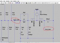
This explains the operation of the FET's in one of my amps. (I know it will mean something to you )
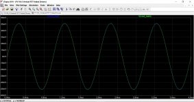
First image is the FET relay with a floating voltage source between G and S.
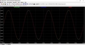
Second image is the FET passing a small AC signal.
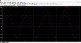
Third image is an even smaller signal. The red trace is the junction of the FET's
Forth image is showing the Vgs voltage under higher drive conditions.
) First image is the FET relay with a floating voltage source between G and S.
Second image is the FET passing a small AC signal.
Third image is an even smaller signal. The red trace is the junction of the FET's
Forth image is showing the Vgs voltage under higher drive conditions.
Attachments
Very impressiveThis explains the operation of the FET's in one of my amps. (I know it will mean something to you
First image is the FET relay with a floating voltage source between G and S.
Second image is the FET passing a small AC signal.
Third image is an even smaller signal. The red trace is the junction of the FET's
Forth image is showing the Vgs voltage under higher drive conditions.
Typical AB power stage
Interested in details of my strange project?
make it easy. Mains switched via relay or triac. E.g. by remote control. To avoid power on thumb a relay shorts output to ground via 10 ohms. The amp state control - dc control etc. then opens the relay and it is out of the signal path. In case of failure it turns off mains triac and shorts supply of amp via triac with a few ohms series resistor. Fast enough to protect speaker.
Thank you for your suggestions!make it easy. Mains switched via relay or triac. E.g. by remote control. To avoid power on thumb a relay shorts output to ground via 10 ohms. The amp state control - dc control etc. then opens the relay and it is out of the signal path. In case of failure it turns off mains triac and shorts supply of amp via triac with a few ohms series resistor. Fast enough to protect speaker.
Actually, I have a crowbar already in place
But I intend to use the output switch for- cases when I don't want to blow the fuses, e.g. overtemp
- avoidance of "plopps"
- (redundancy)
I assume that these cases can be handled either way, using mechanical or solid state relays - both having advantages and disadvantages. I personally prefer the SSRs for their better lifetime and silent switching.
Hi LKA, do you sell these protectors ? I would consider buying them
I am building an amp abut 500 watts rms/channel at 8 ohms.
So, supply is about +/- 92 volts dc and speaker current can be up to 10 - 15 amps
peak.
Hi, no, I do not have any board for selling. Also, my implementation is for maximum 200W. You will need better mosfets (or heatsink) and other detector circuit.
Low Rds is important for high current applications. The IRFP360 is 0.2 ohms which is pretty high when you compare it to other devices, but that FET scores on voltage and current ratings.
I used IRF2907's which have an Rds of just 4.5mΩ and a 75 amp Ids although they have a much lower voltage rating of 75 volts.
I used IRF2907's which have an Rds of just 4.5mΩ and a 75 amp Ids although they have a much lower voltage rating of 75 volts.
Well, as I thougt then
As I've got plenty of the 360's for free they may be good enough för now.
Voltage and current ratings seems ok för a bigger amp, but needs a little more coling.
I also got IRF064 with 0.009 ohm RDSon, but only 55 volts VDS. May be good for smaller amps.
Tested with TLP591 as driver but VGS may be ~7 volts, so using two in series maybe garantees that they give maximum. Also use a Jfet to cut VGS faster, but don't know If it's really nessecary
Best Regards
Figge
Edited Swedish auto correction. It s***s....
Last edited:
- Home
- Amplifiers
- Solid State
- SSR for speaker protection?