For a long time I have been listening to a friend of mine's Luxman 5M20 power amp. A fantastic amplifier designed in the late '70s and still considered one of the best Luxman made. It can easily stand its own on any comparison with a more modern amp in audio quality and else.
Some months ago I decided to start my research to see if it was possible to clone it, but all the active parts are extinct now. So the question was: is it possible to use the Luxman as an inspiration, using modern active transistors?
It's mi belief that you can call something a clone when it's exactly alike, which in this case was not possible. So I decided to call this enterprise "The Shadow". And the first design was to be the Shadow 5M20.
As a start what I wanted to do was to simulate the Shadow 5M20 in Ltspice.
The first thing to do was to find capable replacements for each transistor. So I asked Keantoken to help me navigate this sea and see where we could get to.
The input dual fet was a very delicate point, and looking around on what was available I found the 2N5566 to be a suitable choice. I bought a pair. An LSK389 would certainly work too, but at the time it was hard to find. I didn't want to start this project until I got the dual fet.
So my modeling is all based on the 2N5566 at the input. Of course I tried other duals and even singles to see if they made any difference. But the simulation result changes were minimal.
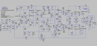
You are free to look for the original Luxman 5M20 schematics. I will only put here the Shadow's.
Let's put the final version I got to, and then explain where it departs from the original design, first to model the electrical characteristics of the original drivers, and second to tame a glitch on the LTP stage.
So now let's see what are the first comments I get
Carlos
Some months ago I decided to start my research to see if it was possible to clone it, but all the active parts are extinct now. So the question was: is it possible to use the Luxman as an inspiration, using modern active transistors?
It's mi belief that you can call something a clone when it's exactly alike, which in this case was not possible. So I decided to call this enterprise "The Shadow". And the first design was to be the Shadow 5M20.
As a start what I wanted to do was to simulate the Shadow 5M20 in Ltspice.
The first thing to do was to find capable replacements for each transistor. So I asked Keantoken to help me navigate this sea and see where we could get to.
The input dual fet was a very delicate point, and looking around on what was available I found the 2N5566 to be a suitable choice. I bought a pair. An LSK389 would certainly work too, but at the time it was hard to find. I didn't want to start this project until I got the dual fet.
So my modeling is all based on the 2N5566 at the input. Of course I tried other duals and even singles to see if they made any difference. But the simulation result changes were minimal.
You are free to look for the original Luxman 5M20 schematics. I will only put here the Shadow's.
Let's put the final version I got to, and then explain where it departs from the original design, first to model the electrical characteristics of the original drivers, and second to tame a glitch on the LTP stage.
So now let's see what are the first comments I get
Carlos
Attachments
Last edited:
This is strictly a personal project I'm sharing with you. I don't think Luxman might care for it. Goldmund clones are more popular here and nobody seems to care. With exactly the same parts types. I don't see why I should be careful.
In any case this is an investigative quest, to see what makes thinks tick.
Q202/202 placement and the different resistors values are exactly right.
Do you want to see the asc files?
In any case this is an investigative quest, to see what makes thinks tick.
Q202/202 placement and the different resistors values are exactly right.
Do you want to see the asc files?
Are you going to tell us why 10 ohm vs. 680?
Well, that's on the original circuit.

They buffer the inputs of the VAS transistors. Known as doing a lot of good. Such buffers are found in Self's single ended VAS, and in Cordell and Groner's differential VAS.I find the placement of Q201,202 to be a bit odd since they are just EF's - not a big deal.
Your Clone is almost a perfect clone
Carlos,
I and Pete would like to see your asc file. Please send also models files applied in your project.
Remember I introduced you simulation files sending you a working template and some devices models file.
In your simulation files there are some differences from original Luxman circuit in output stage. Some changes you did improve amplifier distortions like the connection of output transistors emitter resistor to junction of 470R driver transistors. Why you add there 270pF in the first darlington transistor? Is it your idea or somebody suggested it to you?
There are other improvements that makes lots of results in this old circuit. To get results more near to real amplifier you must also add the signal stage voltage regulator. Luxman makes a little different voltage regulator for signal circuit.
What you did with the Chinese board you order to adapt this circuit?
What are your project objectives?
Regards from SP - Brazil
Ronaldo
Last edited:
For a long time I have been listening to a friend of mine's Luxman 5M20 power amp. A fantastic amplifier designed in the late '70s and still considered one of the best Luxman made. It can easily stand its own on any comparison with a more modern amp in audio quality and else.
Some months ago I decided to start my research to see if it was possible to clone it, but all the active parts are extinct now. So the question was: is it possible to use the Luxman as an inspiration, using modern active transistors?
It's mi belief that you can call something a clone when it's exactly alike, which in this case was not possible. So I decided to call this enterprise "The Shadow". And the first design was to be the Shadow 5M20.
As a start what I wanted to do was to simulate the Shadow 5M20 in Ltspice.
The first thing to do was to find capable replacements for each transistor. So I asked Keantoken to help me navigate this sea and see where we could get to.
The input dual fet was a very delicate point, and looking around on what was available I found the 2N5566 to be a suitable choice. I bought a pair. An LSK389 would certainly work too, but at the time it was hard to find. I didn't want to start this project until I got the dual fet.
So my modeling is all based on the 2N5566 at the input. Of course I tried other duals and even singles to see if they made any difference. But the simulation result changes were minimal.
You are free to look for the original Luxman 5M20 schematics. I will only put here the Shadow's.
Let's put the final version I got to, and then explain where it departs from the original design, first to model the electrical characteristics of the original drivers, and second to tame a glitch on the LTP stage.
So now let's see what are the first comments I get
Carlos
I like this project !
Hi Ronaldo,
That's why I asked what models might be missing. I think I will write a txt file with all the models and zip it all together with the asc files.
About the 270p caps on the base of the drivers, they were Keantoken's suggestion. The idea was to make the circuit mimic the original 5M20 as much as possible. The transistor they used for the drivers were the 2SC1161A/2SA653A (unavailable), with higher capacitance than newer substitute. So he suggested adding two caps: base-ground and base-emitter.
Both caps and several other changes from the original, I intend to add them later on the solder side during the listening tests.
As you see, I didn't include the base-emitter cap as it affected the simulation quite badly. The other cap doesn't seem to affect things much.
The reason why I tried separating the drivers emitter resistors junction from the output , along with 10uF bypass cap was to correct a glitch I had on the sinusoidal signal on the LTP out. If you return things to the way they originally were, you will see what I'm talking about.
Another thing that I added to the original design was C212, the 2.2p feedback cap from VAS-out to the LTP fet. This was to improve the square wave response, which I will upload the asc of too.
About the regulated low current supplies, I am not sure if I will use the original regulator. But that would probably be done during listening tests. I do not know enough of LTSpice to add the supplies on the simulations.
They buffer the inputs of the VAS transistors. Known as doing a lot of good. Such buffers are found in Self's single ended VAS, and in Cordell and Groner's differential VAS.
I knew the purpose, I was simply commenting on the placement in the schematic,
a matter of style but they look like they are trying to be a diff pair. Purely a visual thing.
They are beta multipliers, obviously.
Carlos,
What you did with the Chinese board you order to adapt this circuit?
What are your project objectives?
Regards from SP - Brazil
Ronaldo
Do you have a link to the Chinese board?
Did you consider Sanken's in the output stage?
Yes, I forgot to elaborate on that.
Those Chinese boards looked like a good option for the prototype stage, as it would easy up part of the process.
Those boards were designed for a Goldmund "semi-clone", as it used bipolar outputs instead of Mosfets. When I saw the circuit I had the idea to use them for the Shadow project.
Pcb mono placa amplificador goldmund 2scC5200 saida ajustavel Uma discreta 2sa1943 tubo goldmund amplificador traseiro Frete Gratis em Amplificador de Eletronicos no AliExpress.com | Alibaba Group
I bought a pair of boards and I'm working on how to adapt them. There are two Shadow stages missing on the Goldmund semi-clone: the LTP-VAS buffer and the pre-driver. It should be easy to add two small piggy-backs for them.
But I think there other things to be considered after trying the prototype, like the influence a correctly designed pcb has on the audio quality.
On the prototype I should be using the MJLs for the output. Sankens are not easy to source, and it seems there are many fakes around. It's quite likely I will buy the output transistors directly from On Semi, if they still sell direct. Just to be sure.
Last edited:
Carlos
If you love the sonic signature of this old amplifier, you have the following options:
1- Order a old sample of this product in good working conditions (Best Option, expensive and risk);
2- Make PCB using exactly the same layout and parts. Use also exactly the same circuit structure, transformer type and so on. It will be expensive and difficult as parts are old and rare.
3- Make a new amplifier project with new components and circuits correction. I am sure you will get a best amplifier. It was also done with Goldmund clone and there are lots of solutions (some goods, other very questionable - it will depend of designer skills and dedication of course).
Simulation is a good way to start, but bench tests and audible test will define what you need. If you change amplifier compensation as you did in your simulation file you got a different sonic behavior for sure - and it becomes a new project. It must be done in sonic tests when you listen results.
You can read in HTForum all design criteria I used in my actual amplifier using this same topology. It is a more than 10 years old project.
You know I love this circuit arrangement and I prefer the sonic signature of Mark Levinson's amplifiers with the exactly the same topology but with best circuits solutions.
Good lock
Ronaldo
- Status
- This old topic is closed. If you want to reopen this topic, contact a moderator using the "Report Post" button.
- Home
- Amplifiers
- Solid State
- When a Luxman clone is not a clone