Regarding the input LTP, I think I can safely say that the design allows direct replacement by jfets like the J74 or even the J103 (GR or BL). I found input jfet LTP to have more liquid presentation. I also found similar effect (but cheaper and more accessible) simply by using 22-47 ohm resistors on emitters of the pnp LTP. Tried both modifications long ago on diy Mosfet Citation 12....If the LTP can be balanced (and with it DC offset) with transistor matching that can be done on a cheap DMM, then just tell everybody to buy 10 or 20 and get two nice matches. The KSA992 cost ¢15 in qty. (10), so it's more than cheap enough to not matter....
Mas Indrawan,
In my experience adding 22-47R degeneration to the bipolars of a LTP reduces the transconductance of the stage to the jfet LTP. In both cases you reduce the loop gain of the amp, and thereby reduce the global feedback levels.
The liquid presentation is also a feature of lateral output devices, too, and for the same reason.
GFB also has other effects on amp presentation, including damping factor, FR, and spatiality (imaging).
yth,
Hugh
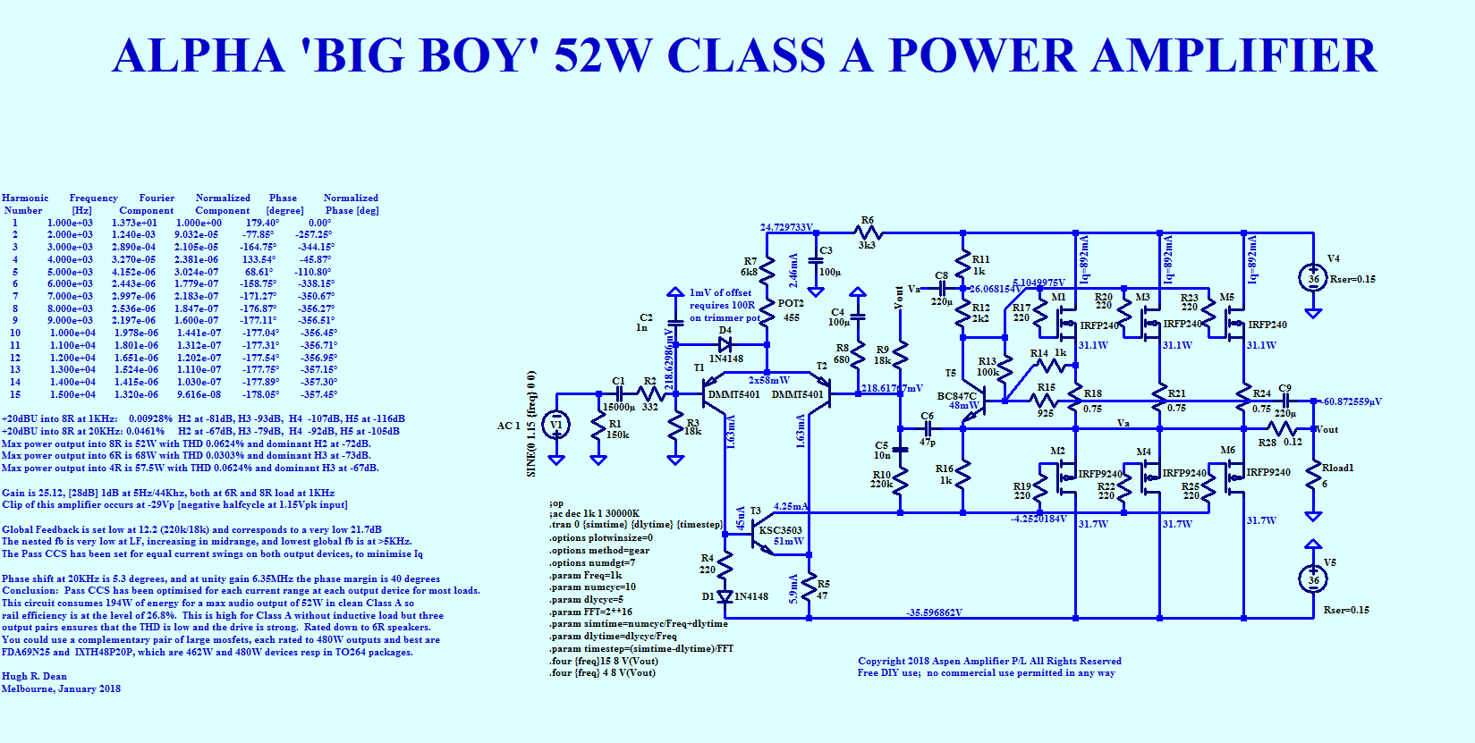
Here is the latest Big Boy 52W amp from Hugh. Now with lower dissipation. Three pairs of IRF240/IRFP9240 are used to approximate the model of the FDA/IXIS single pair. It’s 26% efficient so achieves 52W output for 194W dissipation. Bias is 2.7amps ea or 900mA ea if using three pairs.
Attachments
Thank you Hugh,...In my experience adding 22-47R degeneration to the bipolars of a LTP reduces the transconductance of the stage to the jfet LTP. ...
Yes, I became aware of the many subtle effects later on, transconductance is one, effective input and output capacitance, gain transfer function and others. Come to think of it, this tweak may be less apparent when Vishay 9xxx (with known gain shelving at ~1kHz) is being used, but should help when builders use other p channel vertical switching parts from Harris, Fairchild, Ixys and the likes. Some people like Juma and Patrick found them to be too grainy and prefer the lower transconductance audio type like the Toshibas. The Laterals need higher gain on preceeding stages or the presentation suffers, builds with them on Aleph and F5 topology exhibit lack of dynamics. Like the Fetzilla, the three stage Alpha may prove to have just the right combination.
I found much less information on spatiality, not much more than the references I mentioned in post #47. I suspect but have no proof that spectra and phase of higher harmonic distortion also plays a significant role. Not enough experience under my belt. I try to have 3H at 1W output 15-20dB lower than 2H for stronger effect. Still can not say anything for good level of residual 2H, probably have strong dependency to drivers being used.
Earl Geddes mention that room diffraction and other acoustic effects overwhelm others, yet we still perceive consistent spatial difference attributed to amplifiers with very small measured difference. Perhaps you can share your findings and opinion in the matter to shed more light. They say we can not improve something if we can not measure it.
Hormat saya,
Indrawan
A question regarding choice of heatsinks, I think I have found a suitable 0,4K/W heatsink from our local store for the 20W amplifier version, with an estimated 96W dissipation per channel if I understand it, it would mean one heatsink for one channel would reach a temperature in the vicinity of 60-65C in room?
One thing I am a bit hesitant over is whether the aforementioned heatsink base thickness of 5mm is good enough considering that the heat sources is rather concentrated only over one pair of output FET's.
Thanks Hugh for offering the DiyA community with such an exquisite amplifier circuit and XRK for the build, pictures and measurements.
Regards Michael
Last edited:
Yes, JP, my Maya 200 uses a 350mm x 100mm, this is around 0.27C/watt, and the output M3 holes are precisely 150mm apart.
Would it be better to have the leads on the outputs right at the end, so the outputs are midway in a long line from left to right, again, with holes at 150mm?
Then the two pcbs, one for each channel, could sit side by side with ends of outputs on one heatsink, two for each heatsink as well........
|-----------------------------------------------------------------------|
---- | | ---
---- | | ---
---- | | ---
|-----------------------------------------------------------------------|
I hope you can see my dreadful idea? Think of the three vertical lines being the ENDS of the pcb, left and right, with central three leads for the OPs.
Hugh
There’s benefits to both layouts as the second one Hugh describes is good for his existing heatsinks ") as well as using say, CPU coolers one each for the 52W Big Boy with the same board footprint. The UMS specification is nice because lots of people have those sinks already and easy to get pre-tapped. I wonder if we can make one board for both the 20W and 52W version with only changes being component selection and size of heatsink? Both would be still 2 output MOSFETs. And since Hugh is the creator, he gets his own 150mm layout for the 20W version but which will later become the 52W version with some minor mods. Because, the UMS heatsink can’t handle 180W anyway.
as well as using say, CPU coolers one each for the 52W Big Boy with the same board footprint. The UMS specification is nice because lots of people have those sinks already and easy to get pre-tapped. I wonder if we can make one board for both the 20W and 52W version with only changes being component selection and size of heatsink? Both would be still 2 output MOSFETs. And since Hugh is the creator, he gets his own 150mm layout for the 20W version but which will later become the 52W version with some minor mods. Because, the UMS heatsink can’t handle 180W anyway.
as well as using say, CPU coolers one each for the 52W Big Boy with the same board footprint. The UMS specification is nice because lots of people have those sinks already and easy to get pre-tapped. I wonder if we can make one board for both the 20W and 52W version with only changes being component selection and size of heatsink? Both would be still 2 output MOSFETs. And since Hugh is the creator, he gets his own 150mm layout for the 20W version but which will later become the 52W version with some minor mods. Because, the UMS heatsink can’t handle 180W anyway.
Last edited:
Hi Hugh,
Are you even interested in building the 20W version or are you going to go Big Boy or going home? The 52W layout doesn’t need to be UMS heatsink compliant. If you are only interested in the Big Boy the let’s keep the 20W with UMS so more people can use it. Or, if JPS64 has the time, he can make two separate layouts for the 20W.
Thanks,
X
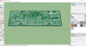
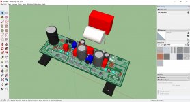
JPS64, Layout and renders look beautiful, btw. Thanks!
Are you even interested in building the 20W version or are you going to go Big Boy or going home? The 52W layout doesn’t need to be UMS heatsink compliant. If you are only interested in the Big Boy the let’s keep the 20W with UMS so more people can use it. Or, if JPS64 has the time, he can make two separate layouts for the 20W.
Thanks,
X
JPS64, Layout and renders look beautiful, btw. Thanks!
Don't make a requirement for new/more holes. Please move mosfets.
https://cdn.shopify.com/s/files/1/1006/5046/files/universal-mounting-specification-v2.1.pdf
Look at diagram labeled "F-5", the third from the top, similar size PCB with Mosfet on bottom edge in existing holes.
https://cdn.shopify.com/s/files/1/1006/5046/files/universal-mounting-specification-v2.1.pdf
Look at diagram labeled "F-5", the third from the top, similar size PCB with Mosfet on bottom edge in existing holes.
Attachments
We are definitely making the 20W compatible with UMS and very similar in layout to F5 board.
Are you referring to the 52W amp here JP? MOSFETs on ends at 150mm CTC but we use plates to clamp them to the Dell CPU heatsink? That's how I hold the MOSFEts at present as you cannot drill and tap into the copper block containing the heatpipes. Only the aluminum frame surrounding it.
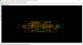
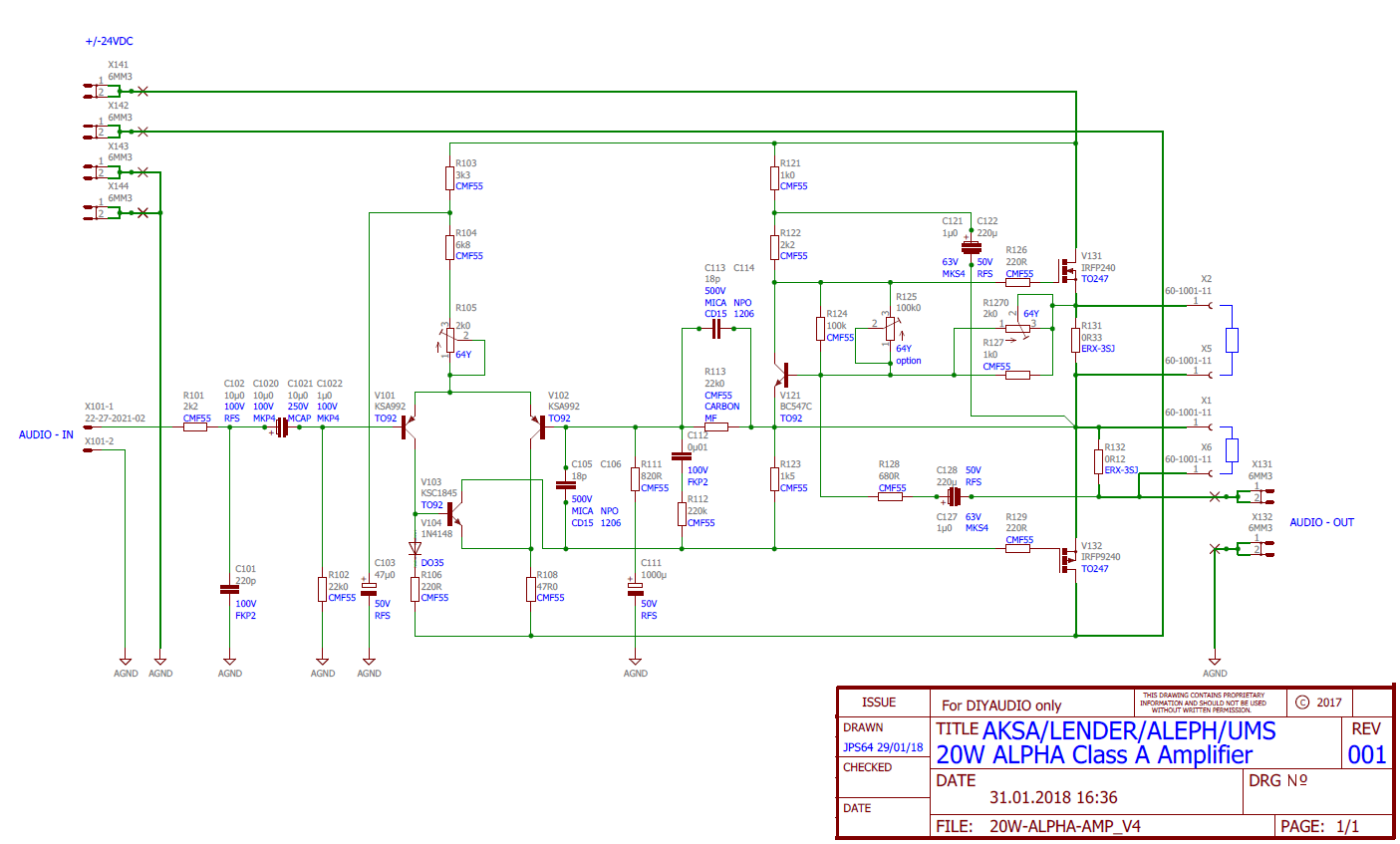
Here is the latest schematic for the ALPHA 20W that will be used for production of the Gerber layout files. Let me know if you see any issues.
We use a aluminium plate to clamp Mosfet on the heatsink without the need of an additional hole: the plate has two hole modulo existing outside holes (80mm).
Are you referring to the 52W amp here JP? MOSFETs on ends at 150mm CTC but we use plates to clamp them to the Dell CPU heatsink? That's how I hold the MOSFEts at present as you cannot drill and tap into the copper block containing the heatpipes. Only the aluminum frame surrounding it.
Here is the latest schematic for the ALPHA 20W that will be used for production of the Gerber layout files. Let me know if you see any issues.
Attachments
Last edited:
We use a aluminium plate to clamp Mosfet on the heatsink without the need of an additional hole: the plate has two hole modulo existing outside holes (80mm).
Why require people to get more parts? If Mosfets attach into existing hole, only M3 bolt and washer are needed.
EDIT: Most recent drawing looks beautiful!
- Home
- Amplifiers
- Solid State
- Aksa Lender P-MOS Hybrid Aleph (ALPHA) Amplifier