That's a classical case of a logical leap, or fallacy.
You blame the scientific / technical institution of using specifications, and the companies and DIYers who take specs seriously, just because some "customers" and companies abuse that institution, trying to cheat people with various tricks.
(...)
Abusement, fraud and cheating, exists in every sector you can imagine. That doesn't mean anything, there will always be a percentage of parasitic and pro-chaotic behavior, like the noise you see on a FFT graph. No system is 100% perfect on this universe.
It's up to us to look for the fine print in datasheets or spec lists and check in depth what we read, in order to avoid being deceived, 99.9% of the time.
Personally, if I discover that a company systematically tries to cheat me, I'll ban that company completely, and most likely I will share my experience with other people in an emphatic way.
Such companies don't have a bright future, or no future at all.
It's on the fundamental principles of marketing the requirement of a great product, and a policy that respects the customer, to ensure a marketing success and start using marketing in the first place.
I never wrote anything about cheating or tricking - in general the people who write the specs don't know what the design compromises are going to be and the designers don't define the specs. In any case, why would it be cheating to supply a product that the market asks for, no matter how stupid that product may be? Whether a perfectionistic designer would like to design a stupid product is a different matter, of course.
Regarding my example, I think it is a quite realistic one, as the vast majority of audio converters have no headroom, see
Intersample Overs in CD Recordings - Benchmark Media Systems, Inc.
A quote from this site:
FAULTY D/A AND SRC CHIPS
Every D/A chip and SRC chip that we have tested here at Benchmark has an intersample clipping problem! To the best of our knowledge, no chip manufacturer has adequately addressed this problem. For this reason, virtually every audio device on the market has an intersample overload problem. This problem is most noticeable when playing 44.1 kHz sample rates.
By the way, the transition bands at high sample rates of most commercial ADCs and DACs also make no sense at all - but apparently they are accepted by the market and that's all that matters for commercial companies.
I may not be as fond of overdesigning as you are, but I have nothing against measurements, calculations and setting targets for performance parameters, just as long as you keep the flexibility to change them when needed.
Last edited:
The DAC clipping you described a couple of times, is obviously a clear case of cheating, tricking and deceving, because the customers that choose a high-performance DAC for its excellent specs and pay a premium, are not informed that it actually produces high distortion in several unexpected cases.I never wrote anything about cheating or tricking - in general the people who write the specs don't know what the design compromises are going to be and the designers don't define the specs. In any case, why would it be cheating to supply a product that the market asks for, no matter how stupid that product may be?
Don't the designers know that their DAC clips a digital signal when it happens to peak at high frequencies? Of course they do, but they don't tell the customer (you can tell how "smart" those companies are, as if one manufacturer produces tomorrow a proper DAC chip and exposes the truth officially, it will gain trust and appreciation and will turn the rest of the faulty chips only good for recycling).
And since the end customers aren't aware of that deception, you can't blame them of wanting a faulty or "stupid" product.
That is a contradiction, a perfectionist designer would like to design a "perfect" product, not a faulty or "stupid" one.Whether a perfectionistic designer would like to design a stupid product is a different matter, of course.
Very interesting, thanks.Regarding my example, I think it is a quite realistic one, as the vast majority of audio converters have no headroom, see
Intersample Overs in CD Recordings - Benchmark Media Systems, Inc.
Can you provide a specific example?By the way, the transition bands at high sample rates of most commercial ADCs and DACs also make no sense at all - but apparently they are accepted by the market and that's all that matters for commercial companies.
I don't accept that negative arbitrary term, for the many positive benefits I have analyzed a few times in our debate when one is aiming unprecedented specs, that go far beyond the resulting awesome specs themselves.I may not be as fond of overdesigning as you are
Good to know.but I have nothing against measurements, calculations and setting targets for performance parameters, just as long as you keep the flexibility to change them when needed.
Last edited:
Can you provide a specific example?
AT1201, but almost any ADC or DAC would do.
The arguments usually given in favour of high sample rates boil down to claiming that the ultrasonic pre-ringing of the DAC interpolation chain might be audible when heard in combination with the rest of the signal. The fact that the human auditory system is not a linear and time-invariant system is then given as an argument to discredit tests done with sine waves that show that ultrasonics are not audible to humans, or it is pointed out that there is spread from person to person and that some young people can in fact hear somewhat above 20 kHz. (Almost no-one seems to take non-human listeners such as domestic cats and dogs into consideration.)
In any case, when you believe that pre-ringing above 20 kHz might somehow be audible in some cases, then aliases and images just above 20 kHz might also be audible. Still, when you look in ADC and DAC datasheets, you'll typically find very wide transition bands at high sample rates that don't prevent aliases or images just above 20 kHz. Needless to say, wide transition band filters take less chip area and are therefore cheaper to implement.
@MarcelvdG
That's a very wide subject, at some point I'll do my own research on what is audible and what is not, including distortion and high sampling rates as I don't trust anyone (and there is no serious/complete research). But I need a decent ES amp and a decent pair of ES headphones first, so it will be done after I'll finish both.
My current impression so far is that while you can't hear individual HF tones, you can hear some complex HF sound combinations like an "airy" atmosphere, so you need more headroom than just 20Khz. Except that, a 384Khz recording will obviously have far less distortion than the guesswork interpolation algorithm that tries to make a full sine wave out of 2 or 3 samples at 44.1Khz at the top of the audio band, and in that case you don't even need an interpolation, so no DAC clipping flaws either.
Of course it is just words for now, as it is too early for any "proof" since it is still under development.
Also I haven't decided the form of the offer (plans, full-kit, pre-assembled), or more than one choice -too early for that too.
In any case, I love providing undeniable proofs about extreme concepts, that says something.
That's a very wide subject, at some point I'll do my own research on what is audible and what is not, including distortion and high sampling rates as I don't trust anyone (and there is no serious/complete research). But I need a decent ES amp and a decent pair of ES headphones first, so it will be done after I'll finish both.
My current impression so far is that while you can't hear individual HF tones, you can hear some complex HF sound combinations like an "airy" atmosphere, so you need more headroom than just 20Khz. Except that, a 384Khz recording will obviously have far less distortion than the guesswork interpolation algorithm that tries to make a full sine wave out of 2 or 3 samples at 44.1Khz at the top of the audio band, and in that case you don't even need an interpolation, so no DAC clipping flaws either.
If you refer to my project,Don’t forget transparency. A diy amp is useless if the results can’t be reproduced independently, and that can only be done if the design is freely and completely available. If the design isn’t available for others to simulate, build, and measure, then it’s just words.
Of course it is just words for now, as it is too early for any "proof" since it is still under development.
Also I haven't decided the form of the offer (plans, full-kit, pre-assembled), or more than one choice -too early for that too.
In any case, I love providing undeniable proofs about extreme concepts, that says something.
Last edited:
Interpolation doesn't involve any guesswork whatsoever, only filtering of spectral copies. You don't have to take my word for that, Claude Shannon already proved in his 1949 article "Communication in the presence of noise" that signals with frequency components below half the sample rate can in principle be perfectly reconstructed (section II theorem 1). The issue with DAC interpolation filter clipping could very well be a reason why many prefer high sample rate recordings, working around the interpolation filter clipping issue without knowing it.
Interpolation doesn't involve any guesswork whatsoever, only filtering of spectral copies. You don't have to take my word for that, Claude Shannon already proved in his 1949 article "Communication in the presence of noise" that signals with frequency components below half the sample rate can in principle be perfectly reconstructed (section II theorem 1). The issue with DAC interpolation filter clipping could very well be a reason why many prefer high sample rate recordings, working around the interpolation filter clipping issue without knowing it.
In practice, that doesn't seem to be the case -you said it yourself (page #1):
So interpolation filters do not sound to me as perfect, distortion-free, otherwise they wouldn't need "headroom" at all to reproduce the digitized waveform faithfully.they have no headroom at all for interpolation filter overshoot and clip when you use them to play music rather than sine waves.
According to Benchmark Media Systems ( Intersample Overs in CD Recordings - Benchmark Media Systems, Inc. ), the main cause of overshoot is the use of peak normalization on a sampled waveform during mastering. They explain how that can amplify the waveform such that the peaks in between the samples exceed full scale. That's the main reason why you need headroom.
Of course any real-life interpolation filter has imperfections, but you can make those arbitrarily small. Using an FPGA board and a 1973 FORTRAN filter design program (James H. McClellan, Thomas W. Parks and Lawrence R. Rabiner, "A computer program for designing optimum FIR linear phase digital filters", IEEE Transactions on Audio and Electroacoustics, vol. AU-21, no. 6, December 1973, pages 506...526), you can easily design digital interpolation filters with linear phase, 140 dB stop band rejection and +/- 0.000002 dB passband ripple.
If you are interested in the subject, PM me and I will send you a list of articles related to interpolation filter design.
Last edited:
By the way, McClellan's code needs a few modifications to run under gfortran, an open-source Fortran compiler; there is one ARCOS that needs to be changed into an ACOS, the double-precision functions now also need to be declared as double-precision in the part of the program from which they are called, numerical values (literals) intended as double-precision numbers need to get an exponent D0 to prevent unintended rounding to single precision and the option to store the impulse response on punched cards is not supported anymore.
I forgot the main imperfection of practical interpolation filters: they need a transition band, for example from 0.45 fs to 0.5 fs. That makes the reconstruction imperfect and can cause overshoots, quite independent of the intersample overshoot issue due to peak normalization. Still, it has nothing to do with distortion in the sense of nonlinear distortion.
How can one expect a fine 20KHz sine signal at a 44 KHz sampling rate.
You expect a miracle from some interpolation technique to reconstruct a sine signal from two samples.
It seems there is a FORTRAN code to do that.
I am amazed to see it has not been recoded in C code since that 50 years old technology.
You expect a miracle from some interpolation technique to reconstruct a sine signal from two samples.
It seems there is a FORTRAN code to do that.
I am amazed to see it has not been recoded in C code since that 50 years old technology.
What abaut re-reading a good EE book? Distortion stems from quantification.How can one expect a fine 20KHz sine signal at a 44 KHz sampling rate.
You expect a miracle from some interpolation technique to reconstruct a sine signal from two samples.
It seems there is a FORTRAN code to do that.
I am amazed to see it has not been recoded in C code since that 50 years old technology.
How can one expect a fine 20KHz sine signal at a 44 KHz sampling rate.
You expect a miracle from some interpolation technique to reconstruct a sine signal from two samples.
It seems there is a FORTRAN code to do that.
I am amazed to see it has not been recoded in C code since that 50 years old technology.
It's not a miracle, just a good low-pass filter. Sampling at 44.1 kHz is equivalent to multiplying the time signal with an impulse series with 44100 Hz repetition rate. The spectrum of such an impulse series consists of all multiples of 44.1 kHz. This means that the original signal gets mixed (in the RF sense of the word) around all multiples of 44.1 kHz, so 20 kHz becomes k*44.1 kHz +/- 20 kHz with integer k. The first image is at 44.1 kHz - 20 kHz = 24.1 kHz, so you need a filter that passes 20 kHz and very much attenuates 24.1 kHz. In fact I like it to pass 20 kHz and very much attenuate anything above 22.05 kHz, so aliases of signals just above 20 kHz are also suppressed. No big deal for a digital FIR filter.
The Parks-McClellan algorithm is quite famous, so I'm sure it has been recoded in any computer language you can think of. As I'm very interested in historical electronics, I prefer to use the original FORTRAN code (also because I could get it for free by just looking up the article in a library and typing in the code). It's probably more readable than C anyway, despite the spaghetti-style programming.
Last edited:
Interesting to take into account when mastering -as I'm into this.According to Benchmark Media Systems ( Intersample Overs in CD Recordings - Benchmark Media Systems, Inc. ), the main cause of overshoot is the use of peak normalization on a sampled waveform during mastering. They explain how that can amplify the waveform such that the peaks in between the samples exceed full scale.
If we can't have a perfect filter, we can't have a "perfect" reconstruction, which is one reason why the use of high sample rates is so more simple and straightforward, and far less dependent on unknown compromising parameters and complexities, and most likely, less costly too, both by eliminating the cost of filters, and because the storage media prices have dropped to ridiculous levels nowadays. That is, when we do have an option.I forgot the main imperfection of practical interpolation filters: they need a transition band, for example from 0.45 fs to 0.5 fs. That makes the reconstruction imperfect and can cause overshoots, quite independent of the intersample overshoot issue due to peak normalization. Still, it has nothing to do with distortion in the sense of nonlinear distortion.
BTW, we are so many decades -36years(!) ahead of CD 44.1Khz it's rather embarrassing that we still use the same format! Think about that.
The physical media should have been replaced by high-resolution ones, decades ago. The only reason they are still produced, is because the technology we adopt (and research too) depends on greed-based profit and big-companies' domination, (profit-driven instead of benefit driven): if it costs a penny less to produce a compact disk, they will keep producing them instead of high-res ones, until human kind populates the galaxy by instant Star Trek-like transportation.
That was extremely funny, as you wrote it on a serious tone:the option to store the impulse response on punched cards is not supported anymore.
"sorry, computer running on coal is not supported anymore"

(I'm a little biased, as I know from a personal research that a computer is possible to be made and run literally on anything that carries any form of energy. Electrons and semiconductors is just one way).
judging from the excellent article you suggested, I'm sure your list will be interesting as well, you've got a PM.If you are interested in the subject, PM me and I will send you a list of articles related to interpolation filter design.
I'm not sure though, whether I'll end up using an FPGA, or a DSP or even a DSP microcontroller (for more flexibility/cost reduction), provided of course I won't find a quality DAC that does not clip at a reasonable cost.
It is always a good idea to read books. Do not speculate how much you know; from information on this site I would conclude: a lot.matze, how does your answer relate to my post ? Does it mean, I know nothing and should read books ?
The question of signal reconstruction after discretisation in time is discussed in detail in many EE and more general books. As pointed out earlier in this thread, Nyquist did seminal work in this area, and results now are part of common canon in information technology.
Matthias
I'm not sure though, whether I'll end up using an FPGA, or a DSP or even a DSP microcontroller (for more flexibility/cost reduction), provided of course I won't find a quality DAC that does not clip at a reasonable cost.
You could buy a Benchmark Media DAC for 2200 euros including VAT (at least that's what they cost down here), or build one of my DAC designs (cheaper, but definitely not cheap, and with lower dynamic range numbers), or take any I2S PCM DAC and attenuate the I2S signal before it goes into the interpolation filter. I still have to work out the details, but I think that can be done with a plain old 74HC158 and a couple of 74HC74's. It won't be perfect because it rounds the signal without any dither, but that's better than clipping.
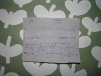
See the attachment for the basic idea. It boils down to playing the MSB twice and delaying everything else by one bit clock period. This gives you a 1 bit (6.02 dB) headroom at the expense of 1 bit of signal level. I thought that by redrawing the logic a bit, the EXOR, inverter and multiplexer could all be made with a 74HC158, but they can't because the 74HC158 multiplexers have a common select input. I've got to think about it a bit more.
Attachments
Last edited:
Ouch, 2200 euros/dollars just for a DAC is way beyond the cost I have in mind, as I don't want it for myself, I want to embedded it as an added bonus and convenience in the ES headphones amp, to ensure no clipping and also have excellent performance -while not necessarily the best-of-the-best on the market due to its low cost.You could buy a Benchmark Media DAC for 2200 euros including VAT (at least that's what they cost down here), or build one of my DAC designs (cheaper, but definitely not cheap, and with lower dynamic range numbers)
The amp itself though, should have incomparably better specs than anything has existed so far (did I mentioned incomparably?) while as a whole (+ the DAC and everything else) should have a very reasonable cost.
I didn't know you have designed a DAC, it reminds me a 10bit ADC I had designed in the 90's using cheap common ICs and discrete components (with a very good performance though), after a very frustrating experience trying for a week to make an ADC chip from NS to work properly, that was proved to be flawed (=completely trash)! (That was a hobby exercise, I couldn't pay a premium to buy an expensive ADC.)
Thanks, but dropping 1 bit would mean a significant digital-to-audio-conversion disadvantage that would cancel its advantage of no clipping. I prefer the opposite approach, that is, to expand the dynamic range instead of reduce it. Ideal would be a 17bit DAC, or a 24bit DAC (that can also be used for 24bit input), scaling up the input signal while leaving the same amount of headroom, eg to 23bits, thus retaining the whole input dynamic range, while avoiding clipping.See the attachment for the basic idea. It boils down to playing the MSB twice and delaying everything else by one bit clock period. This gives you a 1 bit (6.02 dB) headroom at the expense of 1 bit of signal level. I thought that by redrawing the logic a bit, the EXOR, inverter and multiplexer could all be made with a 74HC158, but they can't because the 74HC158 multiplexers have a common select input. I've got to think about it a bit more.
BTW, I appreciate all the help, but unfortunately I can't devote time for that right now, as I am completely overwhelmed by another project that requires a huge amount of research & development that I have to finish first (if everything goes well, it will fund this project too). I barely have time to post a comment once-a-day and I'm only doing it because I like chatting with great people here, about our common passion: electronics.
Last edited:
That was funny, I meant digital to analogdigital-to-audio-conversion
- Status
- This old topic is closed. If you want to reopen this topic, contact a moderator using the "Report Post" button.
- Home
- Amplifiers
- Solid State
- How low can you go?