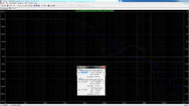
This is the loop gain of my amplifier.
It looks very good, with good PM and GM.
It looks very good, with good PM and GM.
Yes, it is. It proved this compensation is stable.
But, I have some problem if I use BJT output. The value of R29 become too high for loop gain look like as mosfet output.
Btw, the high frequency of my amplifier is very good. I think it is better than my Blameless amplifier with TMC compensation which used better components quality. But it is still in mono, so I wait until my friend build other one.
Bimo this looks very good. If I missed it please forgive, but I don't see any place where the values of the components is listed or stated. Thanks
Because, it is new kind of compensation, I have no confident to share the design. The first prototype have many problem, and some value of components different than the simulation.
Example: The forward voltage of RED LED is different than the model of sim. Un-matching components is too high, I modify the value of DC Servo components to get DC Offset below 1mV. But the compensations never changed.
It is better, you try Dadod's design.
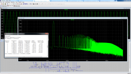
I sim symmetry topology using OITPC compensation. This is the loop gain. Are PM dan GM enough?
Using Miller compensation and lead compensation (Input Inclusive aka Douglas Self):
PM 71 GM 18
THD: 32W/8Ohm, 20kHz -> 0.001720%
THD: 8W/8Ohm, 20kHz -> 0.001887%
THD: 1W/8Ohm, 20kHz -> 0.003326%
SR 40
Using OITPC:
PM 71 GM 14
THD: 32W/8Ohm, 20kHz -> 0.002150%
THD: 8W/8Ohm, 20kHz -> 0.000783%
THD: 1W/8Ohm, 20kHz -> 0.000340%
SR 54
I sim symmetry topology using OITPC compensation. This is the loop gain. Are PM dan GM enough?
Yes.
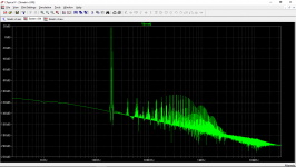
THD at 8 Ohm.
Topology symmetry (VFA) using OITPC, with better VAS (2SC3053/2SA1381) and output TEF.
Very good result.

Very good result.
Yes, it relative simple schematic
which "advanced" compensation. But it is very difficult to get right PM and GM.
And I can not implement it for low gain (below 3x for line pre-amp). If gain too low, sometime it worse than other compensation.
I still learning....
Yes, it relative simple schematic
But it is very difficult to get right PM and GM.
And I can not implement it for low gain (below 3x for line pre-amp). If gain too low, sometime it worse than other compensation.
I still learning....
I never used it for a preamp, there I use current conveyor as a gain block and much simpler compensation, usually a shunt type.
What amp is it?Almost no IMD in audio band.
What amp is it?
This amp using symmetry topology (VFA), OITPC compensation, and output TEF.
This amp using symmetry topology (VFA), OITPC compensation, and output TEF.
Have you built it?
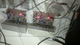
This is my CFA with OITPC which built by my friend. It use cheap components.
My listening impression compared with my amplifier using blameless topology with TMC compensation that use much more expensive components:
This CFA amplifier maybe the best amplifier that I ever heard when produce instruments attack time. Like live. Bass more punch but not deep. The high frequency less airy, with decay time less short.
Bias current for vertical mosfet is set to 150mA. Maybe next time we try higher bias current.
I made simple CFA base on Lazy Cat's VSSA but I added buffer before Lateral mosfet. It more airy than this CFA with OITPC.
I think this amplifier have great potential.
Attachments
This is my CFA with OITPC which built by my friend. It use cheap components.
My listening impression compared with my amplifier using blameless topology with TMC compensation that use much more expensive components:
This CFA amplifier maybe the best amplifier that I ever heard when produce instruments attack time. Like live. Bass more punch but not deep. The high frequency less airy, with decay time less short.
Bias current for vertical mosfet is set to 150mA. Maybe next time we try higher bias current.
I made simple CFA base on Lazy Cat's VSSA but I added buffer before Lateral mosfet. It more airy than this CFA with OITPC.
I think this amplifier have great potential.
Bimo, in my opinion you described exactly what I noticed too with my OITPC amps (CFA or VFA). I think that is because of the open loop bandwidth goes up to 20 kHz or higher.
Bimo, I wonder just how long you will tease us. I hope not much longer. Thanks in all ways.
If you want gerber file of this amplifier, you can ask me to my email: anistardi@gmail.com but I will send the new one but not tested, because the prototype have an error in one transistor.
- Status
- This old topic is closed. If you want to reopen this topic, contact a moderator using the "Report Post" button.
- Home
- Amplifiers
- Solid State
- OITPC - Output inclusive TPC (not TMC)