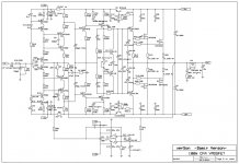
I would like to explain my novel compensation I used lately in all may amps, CFA or VFA with excellent result.
This is a kind of TPC (Two Pole Compensation) but in my opinion much improved with excellent bandwidth Phase Margin (PM) and Gain Margin (GM).
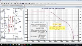
To start with is simple TPC. Choose components give good result but not good enough.
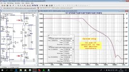
Second step is improved TPC by adding a capacitor parallel to VAS emitter resistor. With the simulation I selected the capacitor value to get good LG (Loop Gain) plot.
Both PM and GM are improved.
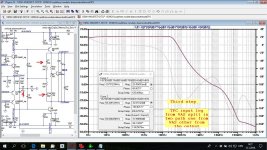
Third set is splitting input leg capacitor and connect half in input leg coming from VAS and half directly from output. By simulation choose values could be different to get best compensation. PM and GM increased enormously.
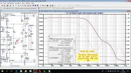
Fourth step is to get it even better decreasing TPC resistor (R1), ULGF decreased to acceptable value.
I hope this can help if someone decided to use this kind of amp compensation.
Intentionally I did not use any math, as TPC calculation was showed before even in this forum. Sorry for my simple common language.
Damir
This is very simple amp, enhanced VAS was not used, with more elaborated amp the result is even better (higher Loop Gain an so on).
This is a kind of TPC (Two Pole Compensation) but in my opinion much improved with excellent bandwidth Phase Margin (PM) and Gain Margin (GM).
To start with is simple TPC. Choose components give good result but not good enough.
Second step is improved TPC by adding a capacitor parallel to VAS emitter resistor. With the simulation I selected the capacitor value to get good LG (Loop Gain) plot.
Both PM and GM are improved.
Third set is splitting input leg capacitor and connect half in input leg coming from VAS and half directly from output. By simulation choose values could be different to get best compensation. PM and GM increased enormously.
Fourth step is to get it even better decreasing TPC resistor (R1), ULGF decreased to acceptable value.
I hope this can help if someone decided to use this kind of amp compensation.
Intentionally I did not use any math, as TPC calculation was showed before even in this forum. Sorry for my simple common language.
Damir
This is very simple amp, enhanced VAS was not used, with more elaborated amp the result is even better (higher Loop Gain an so on).
Attachments
-
 100W-VMOSFET-OITPC-diamondwithtwistOPS-TPC first step.jpg279.9 KB · Views: 2,703
 -
 100W-VMOSFET-OITPC-diamondwithtwistOPS-enhencedTPC second step.jpg279.6 KB · Views: 2,655
 -
 100W-VMOSFET-OITPC-diamondwithtwistOPS-full OITPC third step.jpg279.9 KB · Views: 2,543
 -
 100W-VMOSFET-OITPC-diamondwithtwistOPS-full OITPC fourth step.jpg278.7 KB · Views: 2,547
Last edited:

Hi Damir,
two small questions.
Second: Does this all depend on triple-EF or MOSFET output stage (hf load of output stage to VAS)?
Congratulations again,
Matthias
two small questions.
Does this also work with Darlington VAS? Normally, one then needs the emitter resistor in order to maintain internal VAS loop stability.Second step is improved TPC by adding a capacitor parallel to VAS emitter resistor.
Second: Does this all depend on triple-EF or MOSFET output stage (hf load of output stage to VAS)?
Congratulations again,
Matthias
Hi Damir,
two small questions.
Does this also work with Darlington VAS? Normally, one then needs the emitter resistor in order to maintain internal VAS loop stability.
Second: Does this all depend on triple-EF or MOSFET output stage (hf load of output stage to VAS)?
Congratulations again,
Matthias
Hi Matthias,
If you look at my other amps 200W CFA uses enhanced VAS (or darlington) and it works even better (the same is valid for ordinary TPC and TMC better result if enhanced VAS).
I simulated an amp with triple EF (BJT) and it works as expected.
www.diyaudio.com/forums/solid-state/253039-unique-cfa-120-230w-amp.html
I did not built it but some people started the build. Look at the end of the thread.
I used it in my TT TMC amp, actually converted it to OITPC. This classic VFA with LTP and output triple and it works as expected.
http://www.diyaudio.com/forums/solid-state/182554-thermaltrak-tmc-amp-66.html#post5176442
Damir
In second step, instead of C4 and C5, put it a C+R+L series circuit. I use that in my SARA amplifier from 2012. Of course, you must tune that CRL circuit.
Actually I use R in series with C4 and C5 in some of my more elaborated amps to remove peaking.
Actually I use R in series with C4 and C5 in some of my more elaborated amps to remove peaking.
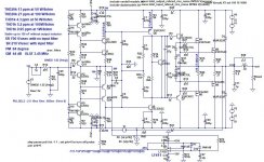
To explain more clearly here is CFA simualtion with enhanced VAS. To remove peaking in the Loop Gain plot resistors of 33R are added in series with C4 and C5.
Attachments
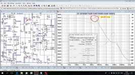

Is that 33r the equivalent to adding a zero?To explain more clearly here is CFA simualtion with enhanced VAS. To remove peaking in the Loop Gain plot resistors of 33R are added in series with C4 and C5.
Is that 33r the equivalent to adding a zero?
Yes, I choose the value by simulation as optimal.
Dadod, instead of 470nF for C4 and C5 put an 10uF. Your peaking will be transformed in a extra open loop gain until at low frequencies.
When I started to use this compensation I tried different values here. For CFA IPS with resistor load (not active load as CM) 470 nF was compromise value between distortion at 20 kHz and the cost. Electrolytic capacitor type is not good choice here and 10 uF does not increase loop gain at low frequencies.
Hi Damir,To explain more clearly here is CFA simualtion with enhanced VAS. To remove peaking in the Loop Gain plot resistors of 33R are added in series with C4 and C5.
I'm still a bit puzzled that you do not have problems with internal VAS loop stability (otherwise some peaking at internal VAS loop ULGF would occur) with the emitter resistor R14 and R52 shorted at high frequencies, see first question in post #2. Is this due to the rather high resistors R20 and R24 at collectors of Q14 and Q2? Do they create some kind of Miller effect with Cbc of these transistors? Or does it rely on the high hf input impedance of driver / ouptut? Or is it a result of your complete OITPC scheme?
Kind regards,
Matthias
Edit: This question relates to the version without R34 / R39.
Last edited:
Hi Damir,
I'm still a bit puzzled that you do not have problems with internal VAS loop stability (otherwise some peaking at internal VAS loop ULGF would occur) with the emitter resistor R14 and R52 shorted at high frequencies, see first question in post #2. Is this due to the rather high resistors R20 and R24 at collectors of Q14 and Q2? Do they create some kind of Miller effect with Cbc of these transistors? Or does it rely on the high hf input impedance of driver / ouptut? Or is it a result of your complete OITPC scheme?
Kind regards,
Matthias
Edit: This question relates to the version without R34 / R39.
Both of those simulations are working amps. When simple VAS used, it is enough to put capacitor with no series resistor parallel to the VAS emitter and there is no peaking.
If enhanced VAS used (EF before VAS tranzistor) than there is need for serial resistor with that capacitor to remove the peaking. I am not quite sure if the amp will be unstable without that resistor, simulation shows peaking in the LG plot but not instability. In real amp I used that resistor.
R20 and R24 are there just to protect VAS from overload in case of high transients at the input. D. Self just ignores that resistor, and I don't understand this. My first "blameless" amp(long time ago) burned the VAS transistor and after that resistor insertion it never happened again.
By the way any internal instability should shows itself in the global Loop Gain plot.
Only if there is such indication, the internal stability simulation is needed.
dadod
Would You mind take a look at my example if it looks kind of right please ?
I would like to give it a try but just to confirm if I am not creating a few transistors bomb
Big thanks
Borys, yes in principle. As you did not provided transistors models I used Cordell's models and get different result, attached.
First so simple LTP and you get unbalanced one. Second why to use output triple with it? By the way, better compensate predrivers instead drivers, I had instability problem with my TT amp (output triples) with compensated drivers.
Damir
Attachments
Hi Damir,Both of those simulations are working amps. When simple VAS used, it is enough to put capacitor with no series resistor parallel to the VAS emitter and there is no peaking.
If enhanced VAS used (EF before VAS tranzistor) than there is need for serial resistor with that capacitor to remove the peaking. I am not quite sure if the amp will be unstable without that resistor, simulation shows peaking in the LG plot but not instability. In real amp I used that resistor.
R20 and R24 are there just to protect VAS from overload in case of high transients at the input. D. Self just ignores that resistor, and I don't understand this. My first "blameless" amp(long time ago) burned the VAS transistor and after that resistor insertion it never happened again.
By the way any internal instability should shows itself in the global Loop Gain plot.
Only if there is such indication, the internal stability simulation is needed.
thanks for that. In my opinion, it is reasonable to look at stability margins in each loop. Even if there is no danger of instability in the whole circuit, some sub-circuits prone to high-frequency ringing might have a negative effect on resilience against e.g. power supply noise or EMI. Additionally, peaking in the global loop sometimes only occurs, if the sub-curcuit in question is already quite close to instability.
But maybe, this all is just over-caution due to strange experiences I made as, let's say, very critical listener ;-).
Kind regards,
Matthias
PS. Comparing again the gain behaviour just past ULGF in the two versions of post #6, I would not exclude a VAS stability issue without R34 and R39.
PPS. In my experience, it saves some phase margin in the VAS loop, if one shorts R20 and R24 with small capacitors, say 100pF.
Hi Damir,
thanks for that. In my opinion, it is reasonable to look at stability margins in each loop. Even if there is no danger of instability in the whole circuit, some sub-circuits prone to high-frequency ringing might have a negative effect on resilience against e.g. power supply noise or EMI. Additionally, peaking in the global loop sometimes only occurs, if the sub-curcuit in question is already quite close to instability.
But maybe, this all is just over-caution due to strange experiences I made as, let's say, very critical listener ;-).
Kind regards,
Matthias
PS. Comparing again the gain behaviour just past ULGF in the two versions of post #6, I would not exclude a VAS stability issue without R34 and R39.
PPS. In my experience, it saves some phase margin in the VAS loop, if one shorts R20 and R24 with small capacitors, say 100pF.
Hi Matthias,
I am not sure about "sub-circuits prone to high-frequency ringing might have a negative effect on resilience against e.g. power supply noise or EMI. Additionally, peaking in the global loop sometimes only occurs, if the sub-circuit in question is already quite close to instability" not enough practical experience on my side. All I read does no support it. Could you show where it is described?
I don't see any indication (post #6) of the VAS stability issue just looking LG plot past ULGF, phase does not dip to low even before ULGF.
I don't remember the posts (the thread became to long) but there was similar discussion with Dave Zen in the 200W CFA thread.
Best wishes, Damir
We agree that R34 and R39 are useful, and they do work in practice. It seems to me that the rest is off-topic to this thread.Hi Matthias,
I am not sure about "sub-circuits prone to high-frequency ringing might have a negative effect on resilience against e.g. power supply noise or EMI. Additionally, peaking in the global loop sometimes only occurs, if the sub-circuit in question is already quite close to instability" not enough practical experience on my side. All I read does no support it. Could you show where it is described?
I don't see any indication (post #6) of the VAS stability issue just looking LG plot past ULGF, phase does not dip to low even before ULGF.
I don't remember the posts (the thread became to long) but there was similar discussion with Dave Zen in the 200W CFA thread.
Best wishes, Damir
Matthias
We agree that R34 and R39 are useful, and they do work in practice. It seems to me that the rest is off-topic to this thread.
Matthias
Yes Matthias you are quite right.
BR Damir
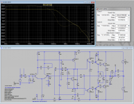
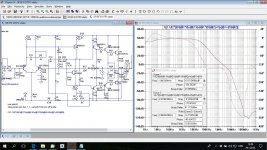
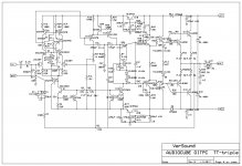
Here are three working amps with this kind of compensation.
1. classic LTP (JFET) enhanced VAS triple OPS
2. CFA with HEXFET OPS
3. CFA with lateral MOSFET OPS
1. classic LTP (JFET) enhanced VAS triple OPS
2. CFA with HEXFET OPS
3. CFA with lateral MOSFET OPS
Attachments

- Status
- This old topic is closed. If you want to reopen this topic, contact a moderator using the "Report Post" button.
- Home
- Amplifiers
- Solid State
- OITPC - Output inclusive TPC (not TMC)