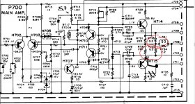
Well I received my parts yesterday, I replaced the R731 which was burnt out and located another burnt resistor R736 and replaced that while i was in there, i changed out capacitors while i was in there, I did fine one not up to spec. I checked the transistors the H702-H703-H710- and H711 checked out fine I did replace the H714 and H715. Put it all back together ran it through my DBT and the relay clicked on, One thing i noticed the light went dim and then came up a little not bright but a little more than dim, do not know if that means anything, so i preceded to check the P800 power supply board and could not get the voltage up to 35v, could that be because i was still on the DBT?? I have not checked the DC offsets yet wanted to take care of the power supply board first. Any feed back would be greatly appreciated
The bulb may be glowing because the bias current is to high. Ideally you need to check the current and see what it is, and if altering preset R719 reduces the current.
Also remember the current drawn by the other channel could be adding to problem.
If the bias seems to adjust OK on test you can then turn it back down until we are sure its all fixed.
Also check the DC offset and make sure it is low. It may be a little way off zero because of the low supply.
Also remember the current drawn by the other channel could be adding to problem.
If the bias seems to adjust OK on test you can then turn it back down until we are sure its all fixed.
Also check the DC offset and make sure it is low. It may be a little way off zero because of the low supply.
Left channel.
Does the 90mv alter as you turn the bias preset ?
Is the 90mv present across ALL four of the 0.22 ohm emitter resistors or are there massive differences in the voltage between them.
(90mv would equate to a current of 4 amps flowing which can't happen with a bulb tester and so something is amiss somewhere)
DEFINITELY not") Always keep the bulb tester in place.
Always keep the bulb tester in place.
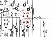
So we need to do a decisive couple of measurements now. I can not see on the diagram where these two test points are in relation to the circuit and so I am assuming they are indeed across one of the 0.22 ohm emitter resistors.
Can you check all four voltages across all four emitter resistors and post the result here.
Always keep the bulb tester in place.So we need to do a decisive couple of measurements now. I can not see on the diagram where these two test points are in relation to the circuit and so I am assuming they are indeed across one of the 0.22 ohm emitter resistors.
Can you check all four voltages across all four emitter resistors and post the result here.
Attachments
No, that would be much to high. You say you have 90mv across the bias test points and the manual says you should have 10mv.
The method in the manual measures across both resistors in series and so that means you should see 5mv across each 0.2 ohm. Yes
Now, if you measured 90mv then that implies you have a current of 0.090/0.4 which would be 0.225A. Far to much.
So first check the voltage across each of those resistors and see what you get.
- Status
- This old topic is closed. If you want to reopen this topic, contact a moderator using the "Report Post" button.
- Home
- Amplifiers
- Solid State
- New Project Marantz 2250b