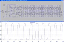
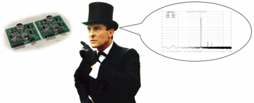
Many output sections are doable, at least in simulation. The attached screen grab shows 16. 10KHz THD driving 10V peak into 4 ohms is 2ppm with +/-18V supply.
This is approx worst case for dissipation. I measure ~500mW per transistor pushing the 10V peak sine wave into 4 ohms, so no heatsinking required.
It keeps going - 14V peak into 4 ohms is ~2.5ppm at 10K. That's 25W, no heatsink")
I had to increase some of the compensation caps a tad to keep it stable, due to the added capacitance of all those output stages.
A quick back of the envelope calculation shows the cost of each output stage to be $2.35, so this sixteen stage mess will come in at $37 for all the output stage bits. Everything else will cost say $8, so cost isn't high.
Real estate wise, on my current prototype each output block is 1.3" x 0.38", so 0.5 inches square. so sixteen would be 8 square inches, or (say) 2.6" x 3".
Oh, the eagle eyed will note I configured this one as an inverting amp. Non inverting performance is identical. Can't think why you'd ever want an inverting power amp though.
I wonder if the BD179/180 is really the best transistor for non heatsink use though? BD139/140 might perform a little better. Will have to keep playing.
This is approx worst case for dissipation. I measure ~500mW per transistor pushing the 10V peak sine wave into 4 ohms, so no heatsinking required.
It keeps going - 14V peak into 4 ohms is ~2.5ppm at 10K. That's 25W, no heatsink
I had to increase some of the compensation caps a tad to keep it stable, due to the added capacitance of all those output stages.
A quick back of the envelope calculation shows the cost of each output stage to be $2.35, so this sixteen stage mess will come in at $37 for all the output stage bits. Everything else will cost say $8, so cost isn't high.
Real estate wise, on my current prototype each output block is 1.3" x 0.38", so 0.5 inches square. so sixteen would be 8 square inches, or (say) 2.6" x 3".
Oh, the eagle eyed will note I configured this one as an inverting amp. Non inverting performance is identical. Can't think why you'd ever want an inverting power amp though.
I wonder if the BD179/180 is really the best transistor for non heatsink use though? BD139/140 might perform a little better. Will have to keep playing.
Attachments
Metal core PCBs are now standard offering at Chinese fab houses for just a minor upcharge. Limitations include: no vias and single layer. Intriguing thought thought and I would like to try on a future Class A amp.
Compared to the 5 dorrah 10 pieces offers I would not refer to the up-charge to Al as minor !
Although in my procrastination of my own projects I did get partway through this:
An externally hosted image should be here but it was not working when we last tested it.
Last edited:
No - I changed R1 to 1K and replaced C1 with a wire link to reduce output offset. There have also been changes to the compensation components.
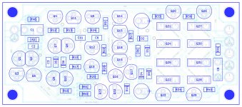
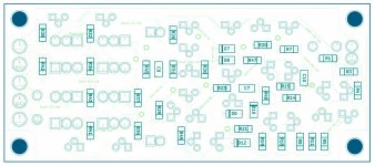
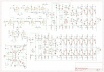
See attachments - schematic PDF, BOM PDF, plus some overlays to assist with assembly, as space limitations mean there are no designators on the silkscreen.
I'm the first to admit my use of MELF resistors is bordering on the ridiculous and adds significantly to the cost - feel free to replace most all the MELFs with 1206 chip resistors - exceptions are R45 and R46.
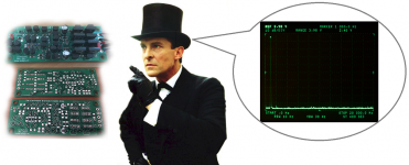
I tried building a BD139 & BD140 version. The simulation was very promising, but with the real thing I have thus far been unable to stop it oscillating without killing the slew rate. The bloody thing oscillates at 45 MHz, which has gotta be some sort of record for these poxy audio transistors. I didn't see the oscillations at first, as they were outside the range of my spec-an (DC-40MHz). They really trash the THD performance. I was able to see them using my CRO, which goes to 100 MHz.
Anyway, the BD179 & BD180 version has thus far been rock solid, with a variety of loads down to 4 ohms, including some fairly large (Vifa P13WH) speakers. Indeed the whole exercise has me wondering why I bother building bigger amps.
See attachments - schematic PDF, BOM PDF, plus some overlays to assist with assembly, as space limitations mean there are no designators on the silkscreen.
I'm the first to admit my use of MELF resistors is bordering on the ridiculous and adds significantly to the cost - feel free to replace most all the MELFs with 1206 chip resistors - exceptions are R45 and R46.
I tried building a BD139 & BD140 version. The simulation was very promising, but with the real thing I have thus far been unable to stop it oscillating without killing the slew rate. The bloody thing oscillates at 45 MHz, which has gotta be some sort of record for these poxy audio transistors. I didn't see the oscillations at first, as they were outside the range of my spec-an (DC-40MHz). They really trash the THD performance. I was able to see them using my CRO, which goes to 100 MHz.
Anyway, the BD179 & BD180 version has thus far been rock solid, with a variety of loads down to 4 ohms, including some fairly large (Vifa P13WH) speakers. Indeed the whole exercise has me wondering why I bother building bigger amps.
Attachments
Last edited:
Since the silkscreen on those boards says "11/2017" but the first message in this thread was posted in 12/2017 , Sherlock Holmes and I conclude: the boards in the photograph do not contain this circuit, designed by suzyj.
Which ones say 11/2017?
Which ones say 11/2017?
These (attached)
Attachments
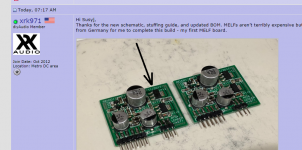
Oh sorry for the confusion, these are a different amp altogether (Aksa Lender preamp) - I was using as an example of my first MELF experience and how the entire stock of mini MELFs in USA are wiped out for some reason at Digikey, Mouser, Newark.
But, I just checked Mouser again, and the 1k R1 for this amp seems to be in stock.
But the next one, the 220R is not available... Ok, so 1206 thick film it is then.
But, I just checked Mouser again, and the 1k R1 for this amp seems to be in stock.
But the next one, the 220R is not available...
Ok, so 1206 thick film it is then.
Last edited:
Attachments

MELF resistors - 3.694 Matches in thousands In Stock at Mouser.
From BOM:
270R Part No 594-MMA02040C2700FB3 - 0 in stock, factory lead time 69 weeks
220R Part No 594-MMA02040C2200FB3 - 0 in stock
10k Part No 756-WRM0204C-10KFI - qnty 1 in stock
Well, some are in stock but many are not.
Hi Suzy,
Thank you! This looks like an amazing small amplifier. Indeed, making a system using an electronic crossover and these would be a killer system!
Best, Chris
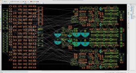
You've clearly been spying! That's exactly what I've been doing this weekend - re-designing my noiseUnit amp (active 2 way with SB12PFC 12cm woofer and NE19CTS 19mm tweeter) to use this amp, or at least this one for the tweeter and the same thing with six sets of drivers (an astonishing 15W) for the woofer.
I'm trying to get it all on one PCB, 10cm x 10cm, so I can get the PCBs cheaply, but my layout thus far looks like it might be a teensy tad longer than that - not to worry!
The thought is to use flat aluminium strips sandwiched between the output transistors as a cheap minimalist heatsink, then put the amp in the speaker's port, where the woofer itself pushes air over it, thus keeping it cool.
It should be applicable to any little two way - or even useful driving mid and tweeter for a thumping big three way system.
There are exactly 100 transistors
I love these simple amplifiers.Attachments
Last edited:
Looks like he nailed it : )
That's gorgeous, Byrtt!
- Home
- Amplifiers
- Solid State
- Cascading diamond buffers - a cheap low THD 10W amp with TIP41C