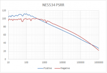
~-50dB for both +ve & -ve @ 100kHz is quite good.I ran this today.
Does PSRR get better with the recommended local decoupling added?Looks good.
Have you noticed any difference with power pins decoupling and Rload change?
George
I would have expected the chip to be tested to give the best results and that would be with the local decoupling already in place.
Yes those plots look good. Both because the rejection is high and because it is similar for each rail.
Which manufacturer's 5534 is this?
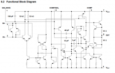
I didn't expect the rails to measure so closely after I had a quick look at the schematic. I'll need to study it more closely. This arose in that other thread to do with bootstrapping the output to the power rails, which has complicated stability implications.
Which manufacturer's 5534 is this?
I didn't expect the rails to measure so closely after I had a quick look at the schematic. I'll need to study it more closely. This arose in that other thread to do with bootstrapping the output to the power rails, which has complicated stability implications.
Last edited:
it's a 5534, the 5532 is arranged a bit differently.Yes those plots look good. Both because the rejection is high and because it is similar for each rail.
Which manufacturer's 5532 is this?
I didn't expect the rails to measure so closely...........
Indeed. I posted the wrong one. Here's the 5534. Pretty similar.it's a 5534, the 5532 is arranged a bit differently.
Attachments
Good point and, more generally, what was the test set-up? How was the psu voltage changed and what was used to measure the output to psu response? What was the output load and the input loading? Power supply voltage?Jack,
was your test with, or without local decoupling?
And what sizes/locations?
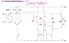
I had my cat edit the original.
Looks like 12pF and 7pF are NFB paths. The 40pF looks more like a positive feed-forward.
So maybe the split NFB paths that lead to nodes that are loosely anchored to opposite power rails explains the closeness of the PSRR of each rail.
Looks like 12pF and 7pF are NFB paths. The 40pF looks more like a positive feed-forward.
So maybe the split NFB paths that lead to nodes that are loosely anchored to opposite power rails explains the closeness of the PSRR of each rail.
Attachments
Last edited:
- Status
- This old topic is closed. If you want to reopen this topic, contact a moderator using the "Report Post" button.
- Home
- Amplifiers
- Solid State
- Who was looking for NE5534 PSRR?