Not exactly. If you mean I mentioned some 1k resistors from post 709, this is stand alone testing of frontend psu without amp with help of 1k resistors. However R10, R11 on the pcb are the same. Zeners on the amp drop voltages, for example, from initial 49V input at 5V zeners to 44 Volts, which appears to be at bases of Q16, Q17, and to 15 Volts at 15V zeners. All these can be checked in the sim.
Light bulb has nothing to do with the sag (which is also present with frontend psu connected directly to mains) which is constant not only in charge time.
R10, R11 values are just right. If you check the sim I can raise them to 1.1k only to maintain 15V at D1, D2. With 2.2K there won't be 15V potential, only just 7-10V.
As I mentioned in previous post, more likely psu sag appears from not proper input voltage setting to shunt psu which my frontend is. Output voltage of shunt psu cannot be the same as it's input voltage.
Judging by the size of the front end toroid this should be able to supply your needs even with shunt load resistors. What are the specifications for this - winding voltages and the regulation%.
If the winding voltage is low and regulation is not tight you might achieve above the voltage nominal figure with no load and have that reduced when the load is applied.
If there is a problem with rating or regulation of your transformer you should connect the primary to the mains to avoid any compromise in that respect.
There is a further need to identify the load where the current is being drawn to - I mentioned some resistor numbers where to measure voltage drops and calculate currents in my last post.
How hard is that to do.
Say that to Lazy Cat. Simple Symetrical Amplifier
Sorry to see that the ballanced potential is not beeing used.
Shunt psu, now you may have an high output resistance....
In witch post is your correct circuit with correct values ?
This Lazy cat circ do have the same issues whatever input trannies you are using. Yes i understand its not yours its your friends circ. The same you tried to fault trace for ore than a year without results?
Sorry to see somone using this topology. the input circuit is a bad topology.
In post One of the Top Solid-State CFA amp design there is psu schematic. I used 50V zeners instead.
How these issues influence or appear in operation of the amp, what are the negative effects? Yes, before I tried flawed balanced input topology.
The toroid has 37VAC secondary without load, maybe 30-40W, I was usung it for two PSUs for both channels with 3mA bias current without issues. I don't know what % regulation it has.Judging by the size of the front end toroid this should be able to supply your needs even with shunt load resistors. What are the specifications for this - winding voltages and the regulation%.
How hard is that to do.
You didn't asked me to measure. The Voltage drop at R10, R11 is 17.5-18V, 17.15-17.6V and keep rising a bit. At R14, R15 is 173.2mV for both. Front end voltage now is 37.5V, rectified voltage is 46V (psu input voltage after rectification). When I connect low wattage bulb 40W, Psu voltage at out is 36V and 36V rectified voltage. In this case the bulb is limiting the current.
Last edited:
In post One of the Top Solid-State CFA amp design there is psu schematic. I used 50V zeners instead.
How these issues influence or appear in operation of the amp, what are the negative effects? Yes, before I tried flawed balanced input topology.
tnx. shunt front end psu.
Works like a capasitor bank then a current sorce then a shunt.
I dont know hov mutch power the shunt is capable of (Q6 and 7).
To increase current from current sorce reduse R3 and R4
Typical 1.8V across LED , 0.6V base emitter T1 and T2.
Max current out is then (1.8V-0.6V) / R3 .
To find value for 100mA it becoms 1.2V /0.1 = 12 Ohm
for 50ma it is 1.2/0.05 =24 Ohm.
Without load the shunt transistor Q6 and Q7 shoul bee able to take (Zener voltage + 1.8V ) multiplyed by current sorce.
(50Volt zener+1.8v) multiply by current sorce with 12 Ohm (100mA)
51.8 * 0.1 is 5.18 Watt.
Front end needs approxymately 40Ma steady state + and minus voltage amp range wich is approxymately 10mA-20 mA dependent on input bias.
That means your powersupply should bee able to deliver minimum 60 mA.
Setting it to deliver 70 mA should give a bit margin.
resistor R3 and R4 to approx 1.2/0.07 = near 17 Ohm
Bleed transistor max power 51.5*0.07 =
I would give that a god start. This is just using Ohms law if i remember right after to long time at school.
Too doo this make shore your transformer has windings to do so. If not use volage doubling for front end.
Last edited:
I dont know hov mutch power the shunt is capable of (Q6 and 7).
To increase current from current sorce reduse R3 and R4
Too doo this make shore your transformer has windings to do so. If not use volage doubling for front end.
Q6, Q7 are MJE15035\34, with 4A Collector Current Continuous, 50W Pd.
I'll use 12-17 Ohm for R3, R4, whatever closer value I find to 70mA. There are prety big heatsinks, which are totaly cold now with current stock values. They only become little warm when PSU On witout load and the LEDs aren't working without load. This is frontend PSU from Roender's FC100 amp.
Perhaps I need to increase secondary windings to 47VAC without load, now it's 37VAC to have 50V out. Maybe it will be enough just only 45V for front end if the main amp PSU will be 40V, for example?
Thanks.
Last edited:
With refference to gnd the measurements are: R11 - 15V\32.9V, R10 - 14.95V\32.6V, R15 - 37.80V\38V, R14 - 37.44V\37.60V
You have roughly 18 ma consumption through the zeners and virtually nil through R14 and R15 which supply the output section.
The current from the output feeds the rest of front end via R19 and R20 - what are the voltage drops across these.
You have roughly 18 ma consumption through the zeners and virtually nil through R14 and R15 which supply the output section.
The current from the output feeds the rest of front end via R19 and R20 - what are the voltage drops across these.
R14, R15 set the VAS bias should be around 15-25mA.
R19, R20 has 0.600V, 0.627V across them.
R14, R15 set the VAS bias should be around 15-25mA.
R19, R20 has 0.600V, 0.627V across them.
Divided by 1500 each that is about 400uA which is about right under static conditions.
I think you made mention of owning a variac which is what a service man would use for setting up an amplifier test? If so why would you not be using that instead of a light globe in the mains connection?
Because light bulb is more informative, can limit the current if something goes wrong.
Regarding voltage sag of frontend psu, as R Dijk stated and according to sim the IPS of the amp requires at least 50-60mA with 4mA bias. My psu with current setting capable of 36mA only.
Regarding voltage sag of frontend psu, as R Dijk stated and according to sim the IPS of the amp requires at least 50-60mA with 4mA bias. My psu with current setting capable of 36mA only.
Q6, Q7 are MJE15035\34, with 4A Collector Current Continuous, 50W Pd.
I'll use 12-17 Ohm for R3, R4, whatever closer value I find to 70mA. There are prety big heatsinks, which are totaly cold now with current stock values. They only become little warm when PSU On witout load and the LEDs aren't working without load. This is frontend PSU from Roender's FC100 amp.
Perhaps I need to increase secondary windings to 47VAC without load, now it's 37VAC to have 50V out. Maybe it will be enough just only 45V for front end if the main amp PSU will be 40V, for example?
Thanks.
NICE!
>I think thats just fine, you have near 5V for regulation. Remember Zener diodes d7 d8 42-43V
transformer voltage * 1.42 minus diode voltage = first capasitor voltage = 37*1.42 - ( 0.6 +0.6 )= above 50v
Use 63V minimum capasitor rating.
Som will claim this is not inough. Due to variation in nett power supply for a few % you may then come close to the voltage the current sorce transistor needs (bc139 bc140) maybee 2v minimum.
Make shore the filter resistors R1 and R2 in powersupply is smal. 1 Ohm or less. (Too avoid much voltage drop)
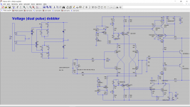
If you use voltage doubling (not increase secondary vindings) you get just abobe 100v for first capasitor bank. that means tooo much change of components with werry litle result. For fun attached example of voltage dobbler (37*1.42*2 minus som diodes= just above 100)
Attachments
Last edited:
Because light bulb is more informative, can limit the current if something goes wrong.
Good luck with that superior attitude -if you keep doing the same things the same results will accrue.
I never dealt with variac in such a way. I guess if I would, there will be a need for power resistors after variac, voltage meter to check the current draw. Light bulb is more simple solution against fault.
Or do you mean to leave current 37VAC secondary and use 42-43V zeners for the same output? (I exchanged 42V zeners to 50V types to raise psu' voltage)
Do you mean when I'll have 47VAC secondary there will be 5V for regulation?NICE!
>I think thats just fine, you have near 5V for regulation. Remember Zener diodes d7 d8 42-43V
Or do you mean to leave current 37VAC secondary and use 42-43V zeners for the same output? (I exchanged 42V zeners to 50V types to raise psu' voltage)
Last edited:
Hi Andriy,
The variac is by far and away the best way to power things up. You should have a built in voltmeter and ammeter (they sell digital one on Ebay for cheap). The variac will allow you to troubleshoot at reduced voltages and the equipment will act properly. I have seen cases where a light bulb in series can cause strange things to happen.
You will even get use to the sound of your variac. I use a 2A, a 3 1/2 A and a 15 ampere with add-on meters. It's the only way to fly. The only person who is happy with a light bulb tester is someone who doesn't have a variac. Or much experience and does have a variac. Use it, get used to it.
-Chris
I never dealt with variac in such a way. I guess if I would, there will be a need for power resistors after variac, voltage meter to check the current draw. Light bulb is more simple solution against fault.
Do you mean when I'll have 47VAC secondary there will be 5V for regulation?
Or do you mean to leave current 37VAC secondary and use 42-43V zeners for the same output? (I exchanged 42V zeners to 50V types to raise psu' voltage)
I mean to leave current 37VAC secondary and use 42-43V zeners for output near 45Volt.
Power supply circ:
(R1 and R2 near 1 Ohm ripple second capasitor bank, R3 and R4 current setting [ (1.8-0.6)/current sett= R3=R4 ], D7 and D8 are voltage out max setting.
voltage first capasitors 37*1.42 -1.2= near 51V without load. should give effectively near 5 volt for regulation when near 45 V out)
Have a nice modifying weekend.
Tnx. I've changed the R3, R4 to 15 Ohm. The front-end voltage isn't sag now (46.5V), but LEDs are off. I measured 1.5V on them.Have a nice modifying weekend.
Shall we finilize the schematic of the amplifier? Any thoughts about R Dijk input stage?
Last edited:

Les of means current regulating transistor is not yet putting out calculated current, but somthing like (1.5volt led -0.6 volt base emitter / 15 Ohm resistanc =60 mA thats just within dynamic ragne and peak no or near zero current for shunt regulation... well if you want a tuch more and light reduse R6 and R7. that is base current for current sorce transistors. reduse somthig like 20% if 10k use 8k ( or multiply by 0.8 if u like that bether ). new output 1.8V LED-0.6v base collector/ 15= 1.2/15 = near 80mA wich makes shore shunt transistors in powersupply output is never of. Some consider this safe side, others BULLSH|T. Remember its still one very important thing here: Its you that is making amplifier NOT everybody else. you want light or not its as simple as that.
finalize ? me ? ive let mee learn that this is a LazyCat construction. I belive he simply love CFA configuration.
I gave one example of one way for stabilizing the construction when driving "heavy capasitive load". And i had a comment or to about transistors for input stage.
2sa979 2sc2240 is cheap value for money transistors. excellent replacement for what you say you are using. But by now you must have become doctor in repairing pcb's ??! Remember cleaning is werry werry werry werry important for performance so you dont make unwanted capacitors and make the construction unnessesearrrrrry dangerous.
Mid sommer sun at its highest and grilling is a must IF possiblle.
Still Nice weekend.
This attached should work. C3, C5 and C12 is stabilizing for bad load. Here is a print screen.
Last edited:
well if you want a tuch more and light reduse R6 and R7
Remember its still one werry important thing here: Its you that is making amplifier NOT everybody else.
finalize ? me ?
2sa979 2sc2240 is cheap value for money transistors. exelent replacement for what you say you are using. But by now you must have become doctor in repearing pcb's ??!
I guess you meant R5, R6
Before we agreed here that the amp is made for comunity, not only for me. Some contribute to design, I'll make a layout.
Sorry, I wrote it in the same post. I asked about finilizing the amp for all contributors, this wasn't addressed especially to you, but you already have taken a part in this.
Which input bjts can you offer as better than these - 2sa970 2sc2240? I'm using these transistors. Why do you think I have to become a doctor? Because I'm making many mods?
Enjoy your weekend!)
Last edited:
Yea i ment R 5 and R 6.
2sa997 and its complement. for lower voltage bc550 bc560. here there is a variation slightly dependent on manufakturer slight regarding noise and current gain grup... witch one where for the porpose of...
slightly rugher for voltage 2N 5401 2N5551 but hav in mind they'r not the best regarding noise. The typical driver for mos and somtime vas stage 2sa1145 2sc2705 may bee hard to trace ( fake on the marked says this forum. 1w 200Mhz 150 volt . It enjoys a lot of voltage.... so on...... but i dont remember the full catalog .... I know many others have good transistor knowledge.
- Status
- This old topic is closed. If you want to reopen this topic, contact a moderator using the "Report Post" button.
- Home
- Amplifiers
- Solid State
- One of the Top Solid-State CFA amp design