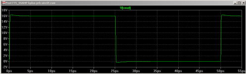
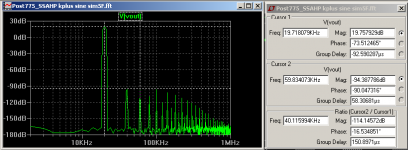
Nice to see you try. Did you add 220R base stopper resistors to drivers Q18,Q19 (sim 5E Post 798)? They were found to be necessary in the simulation with OITPC.I tried this compensation but I left C13 as 320uF, forgot to replace it. The results are worse than with previous compensation. The amplifier is a bit unstable, I can only bias the input only to 3mA, likewise too much noise from the speaker. Here are the scope screenshots without input signal (first start up and couple of minutes run) and two with input signal.
Last edited:
I am aware my sim 5E Post 798 has inadequate PM but I haven't figured out yet how to get better PM with OITPC. In sim 5E you can see I stepped all the OITPC parts one at a time to see what changed what. But none by themselves seem to tweak the PM. So setting it up is more complicated than I first thought.Ian, have you checked that compensation for overshoot?
The phase margin is increased by the means of a resonance after the unity gain frequency. Are you sure the Q of this resonance will remain stable under dynamic conditions considering the Ft of the output transistors may vary 5x or more?
Furthermore this compensation provides a path for frontend rail noise to be injected directly into the VAS input. The simulation does not include modulation of the frontend rails. To fix this the compensation would need to be split into two sections, one for the positive VAS and one for the negative VAS. R44 will be split into two resistors going to their respective rails rather than to ground.
The VAS uses the rail as it's reference node, therefore referencing the OITPC to ground through R44 causes a reference conflict.
Damir ("dadod"), have you given any guidelines on how to set OITPC up? In particular, how to get a good PM (more than 60 degrees)?
Or can someone show us how to get a better PM from sim 5E post 798?
Re: Splitting the compensation and R44 -- sounds like it could be helpful to relax rail decoupling issues. Damir's OITPC amps that I have seen don't split the compensation and R44.
Nice to see you try. Did you add 220R base stopper resistors to drivers Q18,Q19 (sim 5E Post 798)? They were found to be necessary in the simulation with OITPC.
Yes, I added all additional 6C, 3R as per schematic. I had 221R value. C9, C12 were 4.4nF. One exeption I haven't changed C13 to 1uF
I am aware my sim 5E Post 798 has inadequate PM but I haven't figured out yet how to get better PM with OITPC. In sim 5E you can see I stepped all the OITPC parts one at a time to see what changed what. But none by themselves seem to tweak the PM. So setting it up is more complicated than I first thought.
Damir ("dadod"), have you given any guidelines on how to set OITPC up? In particular, how to get a good PM (more than 60 degrees)?
Or can someone show us how to get a better PM from sim 5E post 798?
Re: Splitting the compensation and R44 -- sounds like it could be helpful to relax rail decoupling issues. Damir's OITPC amps that I have seen don't split the compensation and R44.
I tried to explain how to set OITPC here: OITPC - Output inclusive TPC (not TMC)
I used OITPC in my LTP non symmetrical VAS too with good result here. http://www.diyaudio.com/forums/solid-state/182554-thermaltrak-tmc-amp-66.html#post5176442
best wishes
Damir
Better PM for SSAHP with OITPC
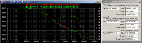
Sim 5E plots attached: PM 92 degree, GM 16dB.
It now gives negligible squarewave overshoot, and THD 3ppm at 20kHz 15Vpk.
AndriyOL, notice the new values -- I hope they work on your board this time. Lag capacitor (C3 in sim 5F) is the the critical one to get it stable in sims; too large and the THD at 20kHz rises. If it still oscillates with the new values try doubling C3 (or larger). All the best.
For sims I found I can step two values with the Tian probe using a second plot expression with @3 and @4 replacing @1 and @2 as below:
-1/(1-1/(2*(I(Vi)@3*V(x)@4-V(x)@3*I(Vi)@4)+V(x)@3+I(Vi)@4
This expression is on my sim 5F below the Tian .step line. Stepping can be seen in the attached "prb" plot; green is R44 15 ohms and red is 10 ohms. Check the ErrorLog for the stepping order: green is 1st, red 2nd.
Stepping in the Tian probe helps a lot to see what each C or R does to the GM and PM. Then you step C or R's with a squarewave to minimize ringing and overshoot. Then check CL with 5nF, 50nF, 1u. I used 500pF as the default for the initial OITP Tian set up.
And a thanks to Dave Zan. The Tian probe does need the output feedback capacitor (C5) after the voltage source as you suggested to get correct results with OITPC. It made all the difference for optimizing for a high PM!
Cheers
Thanks Damir. Some progress on SSAHP sims with OITPC.I tried to explain how to set OITPC here: OITPC - Output inclusive TPC (not TMC)
I used OITPC in my LTP non symmetrical VAS too with good result here. http://www.diyaudio.com/forums/solid-state/182554-thermaltrak-tmc-amp-66.html#post5176442
best wishes
Damir
Sim 5E plots attached: PM 92 degree, GM 16dB.
It now gives negligible squarewave overshoot, and THD 3ppm at 20kHz 15Vpk.
AndriyOL, notice the new values -- I hope they work on your board this time. Lag capacitor (C3 in sim 5F) is the the critical one to get it stable in sims; too large and the THD at 20kHz rises. If it still oscillates with the new values try doubling C3 (or larger). All the best.
For sims I found I can step two values with the Tian probe using a second plot expression with @3 and @4 replacing @1 and @2 as below:
-1/(1-1/(2*(I(Vi)@3*V(x)@4-V(x)@3*I(Vi)@4)+V(x)@3+I(Vi)@4
This expression is on my sim 5F below the Tian .step line. Stepping can be seen in the attached "prb" plot; green is R44 15 ohms and red is 10 ohms. Check the ErrorLog for the stepping order: green is 1st, red 2nd.
Stepping in the Tian probe helps a lot to see what each C or R does to the GM and PM. Then you step C or R's with a squarewave to minimize ringing and overshoot. Then check CL with 5nF, 50nF, 1u. I used 500pF as the default for the initial OITP Tian set up.
And a thanks to Dave Zan. The Tian probe does need the output feedback capacitor (C5) after the voltage source as you suggested to get correct results with OITPC. It made all the difference for optimizing for a high PM!
Cheers
Attachments
- Status
- This old topic is closed. If you want to reopen this topic, contact a moderator using the "Report Post" button.
- Home
- Amplifiers
- Solid State
- One of the Top Solid-State CFA amp design