I am not posting about a very desirable piece of gear, just a recently acquired, old, inexpensive, late 1960's receiver made by Rolland Electronics and branded Rolecor. Probably 12 to 15 watts per channel.
The first thing I did was test the DC offset at the speaker terminals and got nearly 1 volt one each side.
Although my ability to read schematics is minimal, I did spend a fair bit of time looking online for one but without success. No technical info at all actually.
I managed to determine what I thought were the differential pairs on the amplifier boards and substituted newer ones plus replaced all electrolytic capacitors on those boards. This managed to reduce DC offset down to about 0.5 volts.
I started removing and checking (DMM on diode setting) other transistors on the board. There was a pair of TO39's of which one was bad. I replaced those pairs with a complimentary pair of pairs of TO126 transistors which I was told would make a satisfactory replacement. Pinout pattern accounted for.
Still no reduction of DC offset below 0.5 volts.
Have now checked all other TO92 transistors present which tested OK. There are some of what I believe to be Germanium transistors (TO1?) that I have not yet removed and checked.
Can anyone sort of steer me in right direction by advising what other causes might produce DC offset of 0.5 volts and how I can get it down to a more acceptable level?
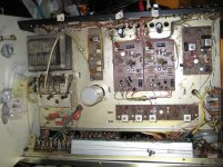
My limited experience tells me this is simple receiver based on how much "open space" there is inside. It is not crowded to the point of anything being inaccessible or even inconvenient to get at.
The first thing I did was test the DC offset at the speaker terminals and got nearly 1 volt one each side.
Although my ability to read schematics is minimal, I did spend a fair bit of time looking online for one but without success. No technical info at all actually.
I managed to determine what I thought were the differential pairs on the amplifier boards and substituted newer ones plus replaced all electrolytic capacitors on those boards. This managed to reduce DC offset down to about 0.5 volts.
I started removing and checking (DMM on diode setting) other transistors on the board. There was a pair of TO39's of which one was bad. I replaced those pairs with a complimentary pair of pairs of TO126 transistors which I was told would make a satisfactory replacement. Pinout pattern accounted for.
Still no reduction of DC offset below 0.5 volts.
Have now checked all other TO92 transistors present which tested OK. There are some of what I believe to be Germanium transistors (TO1?) that I have not yet removed and checked.
Can anyone sort of steer me in right direction by advising what other causes might produce DC offset of 0.5 volts and how I can get it down to a more acceptable level?
My limited experience tells me this is simple receiver based on how much "open space" there is inside. It is not crowded to the point of anything being inaccessible or even inconvenient to get at.
Rolecor brand from the 1960's, predates the Rotel brand which is still produced by the Japanese Roland Electronics Corp. Without schematics for any of those early models though, how can we offer advice? There is a short thread about Rolecor products on AK collectors and repairers forum which will give you a little info but nothing useful.
It's unusual that a small amplifier of that age had a differential input but it may well have had a large capacitor (about 1,500 -2,500uF) coupling the amplifier output to the speakers. This may have become leaky and likely requires replacement. If you have the same 0.5V on both sides of such a cap, that would probably be the situation.
It's unusual that a small amplifier of that age had a differential input but it may well have had a large capacitor (about 1,500 -2,500uF) coupling the amplifier output to the speakers. This may have become leaky and likely requires replacement. If you have the same 0.5V on both sides of such a cap, that would probably be the situation.
Rolecor brand from the 1960's, predates the Rotel brand which is still produced by the Japanese Roland Electronics Corp. Without schematics for any of those early models though, how can we offer advice? There is a short thread about Rolecor products on AK collectors and repairers forum which will give you a little info but nothing useful.
It's unusual that a small amplifier of that age had a differential input but it may well have had a large capacitor (about 1,500 -2,500uF) coupling the amplifier output to the speakers. This may have become leaky and likely requires replacement. If you have the same 0.5V on both sides of such a cap, that would probably be the situation.
There is such a single large capacitor. I thought it was odd for it to only have two terminals as the only other single large cap I've seen on a stereo chassis was inside a friend's large Marantz receiver but it was a dual layer.
The value of said cap is 63V 2200uF. The local shop I go to has a 100V 2200uF on their website but out of stock. Another shop also has one listed on their website but it's farther afield and more expensive.
If local is a no go, I'll get one sent from one of the usual online vendors. That's always my Plan B as it involves a 100KM round trip to avoid the extra time and expense of international shipping and the Canadian duty charged if shipped across the border.
Ian, if only I had half the smarts you do. But, if that was so, I'd be tinkering with something simpler.
EDIT:
"There is a short thread about Rolecor products on AK collectors and repairers forum which will give you a little info but nothing useful."
Yes, as mentioned I spent considerable time looking for info on this Rolecor so became aware of it's department store heritage and the Rotel connection. No doubt I read through those AK threads. I thought I had some luck once as a contributor posted photos of an old Rotel which resembled this Rolecor - including that single large capacitor. Also the manual was uploaded. But unfortunately after studying it, even with my rudimentary grasp, I could see the circuitry and component complement was considerably different.
Last edited:
So old means that it might even be a transformer driven power amp.
In that case there is no DC NFB, no differential pairs of course, and output offset depends on bias string matching, which is somewhat random/iffy to put it slightly.
Are you sure it is a split supply amplifier?
If it´s a capacitor coupled single supply one, which I suspect, then DC offset is irrelevant.
A single 63V, 2,200uF cap could also just be the smoothing cap for the common, single voltage power supply. I should have added that a single supply amplifier requires only one output capacitor - but that means one for each channel, or 2 in total. That won't be an output capacitor, if it's the only large cap. The 63V rating also reads like a more recent replacement but check the voltage on the cap's terminals. If negative is ground and the positive terminal is around 50V, that should be the situation instead. If looking for a replacement, the voltage rating needs to be at least 15% higher than the smoothed DC supply. The maximum capacitance allowable will be limited by the size of diodes which could pop with inrush current on startup. They are probably only rated at 1A continuous but can handle considerably more as a peak charging pulse current. A 1A diode bridge should tolerate up to 3,300uF though.
The main smoothing cap or caps are usually located near the rectifier diodes or bridge but who knows how this one is arranged. Pics, top and bottom of the innards would help a lot to identify the major parts and maybe deduce the general circuit too. I also suspect this is going to have a single rail power supply and a quasi-complementary output stage, as the later dual-rail Rotel series amplifiers and receivers did. If the power transistors (2 per channel) are all the same type (i.e. not complementary NPN/PNP types), it will assuredly be a "quasi" design.
The main smoothing cap or caps are usually located near the rectifier diodes or bridge but who knows how this one is arranged. Pics, top and bottom of the innards would help a lot to identify the major parts and maybe deduce the general circuit too. I also suspect this is going to have a single rail power supply and a quasi-complementary output stage, as the later dual-rail Rotel series amplifiers and receivers did. If the power transistors (2 per channel) are all the same type (i.e. not complementary NPN/PNP types), it will assuredly be a "quasi" design.
digikey ships to canada without customs people report, through some sort of cross border fiddle. They are in Minnisota. Use royal mail instead of UPS, if something changed and there is a customs charge- - RM doesn't charge a customs loan fee as UPS does.
Farnell probably has a warehouse in CA - they are my first line parts house. US warehouse has a lot of 1000, 2200, 3300, 4700 caps. Look under aluminum electrolytic caps, snap in package (not axial leaded, that is now obsolete). If the short pins won't fit your board, solder a splice on or use a cinch solder terminal strip. Use glue to keep the cap from flying around in handling, like 3M weatherstrip adhesive.
And there is a supplier in Vancouver I found in a search once, Bennet's ?, Bailey's? something.
digikey ships to canada without customs people report, through some sort of cross border fiddle. They are in Minnisota. Use royal mail instead of UPS, if something changed and there is a customs charge- - RM doesn't charge a customs loan fee as UPS does.
Farnell probably has a warehouse in CA - they are my first line parts house. .
Digikey is also in Manitoba and Newark is in Ontario. Digikey and Mouser both offer free overnight shipping to Canada, no need to use snail mail. I still find it hard to believe they don't offer better service to the US customer base. Electronic parts are duty free coming from the US to Canada, so unless you are using DHL there's no extra fees.
Thanks for all the info re parts sources.
I have obtained from Mouser & Digikey in the past - primarily Mouser and even Newark Element 14. Although Mouser / Digikey have Canadian web addresses, I assumed that both shipped from the US. They both have a basic shipping rate via USPS of 6 or 8 dollars but that is to a depot called Package Express in Sumas, WA to which is a 2 hour round trip. I am gun shy about shipping to my home address, Those times I've done so (including electronic parts) I've been nailed with either customs or brokerage fees. On weekdays I am away from home 5AM to 8PM so never home when such things arrive so must always drive to whichever outlet it winds up at. Even just a few small items is sent in a box too large to fit in my mail box of the building I live in. I had a $25 USD turntable headshell sent to my home address not long ago and by the time the smoke had cleared it was $76 CAD.
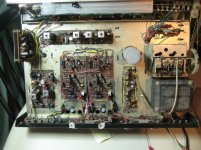
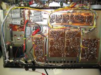
As far as this receiver goes, I appreciate the offers to provide opinions based on photos. I hope those I have taken are sufficient. It will probably be evident but they are after I have replaced certain components therefore do not depict what was on the boards originally.
Adjustment pots were mentioned previously and there are two on each board - a large one and a small one. I have encountered bias adjustment pots before but in conjunction with service manuals. As there is no manual for this unit, I have no clue what either of these two does.
Some additional info:
With the exception of that single large 63V electrolytic, I do have replacement capacitors for all the remaining original grey Elna electrolytics. I have just not gotten to then yet.
The voltage to that 63V capacitor is 47 volts.
I was somewhat less than diligent over the last couple of days. When first obtained, the receiver exhibited nearly 1V DC offset on each channel. After installing what electrolytics I did replace, DC offset went to 0.5V each channel.
But I got lazy. Since Both were more or less symmetrical, I expected them to stay that way so only bothered checking one side. After replacing the original TO39 pairs (2SA & 2SC497) with TO126 pairs (KSA1220 & KSC2690) I saw no change to DC offset in the channel i was monitoring but the other, I learned yesterday, was 11V and I'm unsure as to why this would be.
And apologies for the filth. A brush 'n' blow was going to be my final act.
EDIT: I got a NAD 710 receiver some time ago and checked it's DC offset early on and it was all over the map. I learned later this was because it was capacitor coupled. Although DC offset with the Rolecor appears constant (although grossly imbalanced) is it possible it too is DC coupled? I read recently, where it was alluded to that high-ish DC offset in capacitor coupled amplifiers was normal.
I have obtained from Mouser & Digikey in the past - primarily Mouser and even Newark Element 14. Although Mouser / Digikey have Canadian web addresses, I assumed that both shipped from the US. They both have a basic shipping rate via USPS of 6 or 8 dollars but that is to a depot called Package Express in Sumas, WA to which is a 2 hour round trip. I am gun shy about shipping to my home address, Those times I've done so (including electronic parts) I've been nailed with either customs or brokerage fees. On weekdays I am away from home 5AM to 8PM so never home when such things arrive so must always drive to whichever outlet it winds up at. Even just a few small items is sent in a box too large to fit in my mail box of the building I live in. I had a $25 USD turntable headshell sent to my home address not long ago and by the time the smoke had cleared it was $76 CAD.
As far as this receiver goes, I appreciate the offers to provide opinions based on photos. I hope those I have taken are sufficient. It will probably be evident but they are after I have replaced certain components therefore do not depict what was on the boards originally.
Adjustment pots were mentioned previously and there are two on each board - a large one and a small one. I have encountered bias adjustment pots before but in conjunction with service manuals. As there is no manual for this unit, I have no clue what either of these two does.
Some additional info:
With the exception of that single large 63V electrolytic, I do have replacement capacitors for all the remaining original grey Elna electrolytics. I have just not gotten to then yet.
The voltage to that 63V capacitor is 47 volts.
I was somewhat less than diligent over the last couple of days. When first obtained, the receiver exhibited nearly 1V DC offset on each channel. After installing what electrolytics I did replace, DC offset went to 0.5V each channel.
But I got lazy. Since Both were more or less symmetrical, I expected them to stay that way so only bothered checking one side. After replacing the original TO39 pairs (2SA & 2SC497) with TO126 pairs (KSA1220 & KSC2690) I saw no change to DC offset in the channel i was monitoring but the other, I learned yesterday, was 11V and I'm unsure as to why this would be.
And apologies for the filth. A brush 'n' blow was going to be my final act.
EDIT: I got a NAD 710 receiver some time ago and checked it's DC offset early on and it was all over the map. I learned later this was because it was capacitor coupled. Although DC offset with the Rolecor appears constant (although grossly imbalanced) is it possible it too is DC coupled? I read recently, where it was alluded to that high-ish DC offset in capacitor coupled amplifiers was normal.
Attachments
Last edited:
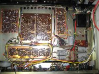
That amplifier has one main power cap (lots of little ones) and two Output caps (which appear to be new).
With NO load, there WILL be "DC" at the speaker terminals. There is a large thump at power-up. With speaker, the output cap will charge-up and the output DC voltage fall exponentially to zero. With no load at all, the output cap has no charge path and the speaker terminal will sit at half-supply "forever". This amp has 1.5K resistors from cap to ground which will tend to zero but very slowly. And if those caps leak, never quite zero. In fact a 1,000uFd cap is likely to leak near 1mA, which in 1.5K would be 1.5V, so "nearly 1V" is on the good side.
Put a 10-100 Ohm resistor on the speaker terminal. Power up, wait. If it goes down and down to below 1V, I would forget about it.
I would be more concerned that the *other* side of the cap sits near half the supply voltage, a happy amplifier ready to swing either way. If it is a 40V supply, it may sit at 16V or 22V, these old amps were not precision DC machines (also you "center" bias allowing for sag). An unhappy amp will show 2V or 38V or worse.
Good pics and I can only agree with PRR's comments and suggestions.
How about the output transistors though - Those little TO39 size cans won't be capable of 12W and neither will the KSA1220/C2690 replacements be. Even with heatsinks, I think only a few watts would be possible. Assuming those are actually the driver transistors, where are the output transistors? Perhaps on the rear panel but are they all the same type?
How about the output transistors though - Those little TO39 size cans won't be capable of 12W and neither will the KSA1220/C2690 replacements be. Even with heatsinks, I think only a few watts would be possible. Assuming those are actually the driver transistors, where are the output transistors? Perhaps on the rear panel but are they all the same type?
My oversight, the output transistors are not shown. They are two pairs of 3055 (can't recall prefix). Those that were on the amplifier were from three different manufacturers. I had the notion that output transistors should all be by the same maker so replaced them with new ones. I did that after doing what replacing I did on the boards.
It may or may not be relevant but once those new 3055's were in place, a DBT glowed quite brightly. Subsequent one by one removal and DMM checking revealed one was bad. I did not test them prior to putting them in so do not know if it was already faulty or suffered damage somehow after putting it in. I'm at a loss to imagine how or why that could have happened because to the best of my knowledge, I patterned installation of components on the board the same way as the originals.
In any case, I substituted one of the original 3055's after checking that it was OK. The DBT. (60 watt) still illuminated but at much lower intensity - sort of a dull orange.
It was about that time I resumed measuring DC offset on both channels and saw the same 0.5 volts on the one I was monitoring but 11 volts on the one I ignored.
FWIW, I will be picking up a couple more new 3055's today. Might be futile, but at least they will all be alike.
I bought in a 1980's Maplin 225wrms amplifier with 2n3055/mj2955 output transistors missing. I bought in brand new ones and the amp oscillated badly.
I tested the new transistors and they had much more gain than the spec for the original transistors. I increased the VAS capacitor a little and that stopped the oscillation.
I tested the new transistors and they had much more gain than the spec for the original transistors. I increased the VAS capacitor a little and that stopped the oscillation.
After reading the recent opinions, it seems that there was no problem to start with if 900mV offset was normal. But there is a problem now.
If bridging the +/- speaker terminals with a resistor (I used 5W 47 ohm) was to reduce that number, it did. The left side with 0.5V became about 12mV and the right side with 11V became about 8.5V and that resistor heated up.
So somewhere along the line I goofed. I had to have installed something incorrectly to create such a disparity.
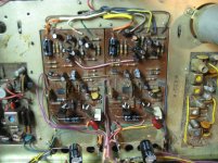
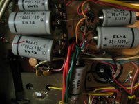
I am very glad I did have a "before" photo of the boards after all that I could refer to because I installed one of those new 1000uF coupling caps backwards.
Since both boards were twins of each other regarding capacitor polarity, I assumed (why oh why do I still do that) that those larger caps would be likewise. But, on examining that photo, I saw right away they were mirror image.
I reversed the "offending" capacitor and with those resistors in place, I now get 12mV DC offset on each side. Without resistors - 0.5 volts.
I feel somewhat elated now that both channels are equal.
Thank you guys for the explanation.
I made a decision yesterday that I wonder if I can stick with and that is to stop looking for old audio gear. I have very little time at home anymore and seem to be spending all of it fiddling with the hardware I manage to find.
I also have a vinyl and tape obsession and wonder why am I not spending time listening to all the recordings I have instead of with what amounts to the uneeded gear required to play it?
Wish me luck.
If bridging the +/- speaker terminals with a resistor (I used 5W 47 ohm) was to reduce that number, it did. The left side with 0.5V became about 12mV and the right side with 11V became about 8.5V and that resistor heated up.
So somewhere along the line I goofed. I had to have installed something incorrectly to create such a disparity.
I am very glad I did have a "before" photo of the boards after all that I could refer to because I installed one of those new 1000uF coupling caps backwards.
Since both boards were twins of each other regarding capacitor polarity, I assumed (why oh why do I still do that) that those larger caps would be likewise. But, on examining that photo, I saw right away they were mirror image.
I reversed the "offending" capacitor and with those resistors in place, I now get 12mV DC offset on each side. Without resistors - 0.5 volts.
I feel somewhat elated now that both channels are equal.
Thank you guys for the explanation.
I made a decision yesterday that I wonder if I can stick with and that is to stop looking for old audio gear. I have very little time at home anymore and seem to be spending all of it fiddling with the hardware I manage to find.
I also have a vinyl and tape obsession and wonder why am I not spending time listening to all the recordings I have instead of with what amounts to the uneeded gear required to play it?
Wish me luck.
Guess the wrongly installed electrolytic was in the channel labelled »1«? Your pics show orange and pink wires coming from the power amp PCBs. These need to be connected to the 'lytics' positive terminals, as in channel 2.
I'd replace at least the erratically reversed capacitor by a new one, it might have become severely damaged or unreliable at least. Better, replace both by axially leaded new ones with a capacity of 2,200 µF, as the LF roll-off for 1,000 µF @ 4 ohms is meagre 40 Hz.
Best regards!
I'd replace at least the erratically reversed capacitor by a new one, it might have become severely damaged or unreliable at least. Better, replace both by axially leaded new ones with a capacity of 2,200 µF, as the LF roll-off for 1,000 µF @ 4 ohms is meagre 40 Hz.
Best regards!
That's a great result and you were so close by our own efforts. There may be a few finishing details to ensure a lasting repair but at least you succeeded and learnt a few new things in the process. I know quite a few guys who've learned very little over the years they've tried repairing electronic devices. Just consider that you're a long way ahead of them and each repair gives you more experience - if you can carefully choose the jobs such that you aren't thwarted by complexity or parts supply issues.
There are no doubt "finishing details" that could be performed but at the moment I am inclined to leave well enough alone. It is not exactly what I would consider a highly desirable unit and was purchased solely because I thought it was an oddball. I guess something made for sale in an Eastern US department store winding up in Western Canada does make it a bit unique - at least around here.
There is little online info on the Rolecor brand but there did appear to be two models below this one.
Is there any measurements I can take / calculations I can make that would determine what it's power output is?
For instance, does the 47 volts I measured and it's using two 2SN3055 output transistors per side say anything?
You turn the volume knob up until the sound is a little strange, then back off slightly (the sound you're looking for is clipping) Compressed pop music & commercials is the best source. classical music actually varies in voltage below max for minutes at a time.
You put an 8 ohm, or on recent units, 4 ohm resistor of suitable power rating on the output. Instead of the speaker. For rough approximation you can use the speaker. Don't short the speaker terminals together while doing this, it blows up transistors. I use extra wires to run the meter feed off to the sides, then alligator clip leads on the probes. The rubber insulated ones so they don't short together.
You take an ANALOG voltmeter with a 20v or 50 v AC scale, and measure the peak voltage.
P=V^2/R
I used to get pretty good results from $6 R**** S**** meters. Their pointers were pretty fast, my $285 Simpson meter pointer is a little slow.
In the very early versions of the 2n3055 the output voltage was about 1/3 the rail voltage, but later higher gain transistors can go to 1/2. 2SN3055 sounds 1978 or later.
How long the unit can sustain this voltage is the differnece between peak, music power, average or RMS watts. Most receivers had wimpy transformers and would peak out much more watts than they could sustain. Heat sink capacity is another limit to sustained watts. Doubling up the output transistors lengthens the time that they can put out a given wattage.
Last edited:
- Status
- This old topic is closed. If you want to reopen this topic, contact a moderator using the "Report Post" button.
- Home
- Amplifiers
- Solid State
- Other than differential transistor pairs, what else can cause high DC offset?