
Ok, D7 is a 1N4004 diode, is there any one in particular in should get? I see there is glass or silicone.
This type ok?
This type ok?
Hi ok, you must be getting -62vdc at that point where D7, D8, C37 and R62 meet then otherwise you wouldn't get 125v across the resistor.
Yeah voltages are nice, I suggest rechecking voltages around the protection circuit.
So D7 is probably ok.
Double check your measurement at the emitter of Q20
Yeah voltages are nice, I suggest rechecking voltages around the protection circuit.
So D7 is probably ok.
Double check your measurement at the emitter of Q20
Last edited:
I went a little mad earlier and got my pins mixed up when checking the voltages on the transistor legs, I didn't realise the pin layout is from below and not from above the component. I had wasted a bit of time trying to figure out where things weren't making sense.
I've done the voltage checks again this time without the test bulb and I've found something weird.
Here are the measurements I've made.

Now the reading at the junction between D7 and D8, if I measure with the negative on the speaker post it won't read anything but if I take it from the ground end of C37 I'll get -132.7. I found this to be strange.
I'm also getting 0.5VAC where the red star is and I get 0v where you have 9.4v at Z7.
I'm yet to try taking Q20 to Q23 out.
At Z12 is that the voltage across the component?
I've done the voltage checks again this time without the test bulb and I've found something weird.
Here are the measurements I've made.
Now the reading at the junction between D7 and D8, if I measure with the negative on the speaker post it won't read anything but if I take it from the ground end of C37 I'll get -132.7. I found this to be strange.
I'm also getting 0.5VAC where the red star is and I get 0v where you have 9.4v at Z7.
I'm yet to try taking Q20 to Q23 out.
At Z12 is that the voltage across the component?
Z12 is the voltage across the circuit.
Ok so does your version have DMOD?
I think we can rule out that part of the circuit and look at the issue being Q25 is not turning on. Maybe try a different transistor in Q25 leaving out the rest of Q20-23. It looks like Q25 is not turning on.
Ok so does your version have DMOD?
I think we can rule out that part of the circuit and look at the issue being Q25 is not turning on. Maybe try a different transistor in Q25 leaving out the rest of Q20-23. It looks like Q25 is not turning on.
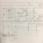
Right here is my last stab at this.
Here are measured voltages in red now.
Q25 should be turned on by the voltage present at its base.
This then drops the voltage at the. Are of Q24 which in turn turns on Q24.
The voltage is then dropped across R68.
This will turn on Q45.
I would measure each side of R68
You could also remove Q45 and see what measurements you then get.
Attachments
Devinder, did you float the o/p the amplifiers out stage from the protection circuit to see if the protection circuit is working by itself?.. and work on things in stages.
The basic of amplifier repair is not to just start replacing parts and see if it will power back up, but to ensure each stage is working and correct things where needed.
The t03 mosfets there outer case is connected to the output of this amplifier.
Start at the input circuits then to the tail pairs/ vas stage and output stages..
See how you get on.
Yes it's been rounded down for quite a while now to the protection circuit. And in fact to the later half of the protection circuit. Voltages from a working amp are above in my post in red and Devinder has given voltages from his.
Other issues have been found along the way including input opamp, unhappy zener voltage in the amplifiers differential input stage supply.
The issue is in the area of Q24, Q25 from what can be seen.
Devinder, can you confirm the voltage across SOFTSTART which is across the mains so be careful! It is a resistor shown on the PSU page.
Also the voltage across R152 in the protection circuit.
I took some more measurements today but I forgot to measure across R68 and R152, I'll do that in the morning.
I'll also remove and check Q45 tomorrow.
Here are the measurements I took.

At Z7 I'm getting 200mVAC but it seems to increase to 200mVC from 0.
At the soft start resistor I'm getting 3.5VAC.
I'll also remove and check Q45 tomorrow.
Here are the measurements I took.
At Z7 I'm getting 200mVAC but it seems to increase to 200mVC from 0.
At the soft start resistor I'm getting 3.5VAC.
R68, 197mVDC I'm also getting a bit of ac there, around 5mVAC
R152, 57mVDC
I've removed Q45 and it seems ok via those checks I found to do. Would you like me to measure the voltages in the areas that are different to yours with Q45 removed?
R152, 57mVDC
Right here is my last stab at this.
Here are measured voltages in red now.
Q25 should be turned on by the voltage present at its base.
This then drops the voltage at the. Are of Q24 which in turn turns on Q24.
The voltage is then dropped across R68.
This will turn on Q45.
I would measure each side of R68
You could also remove Q45 and see what measurements you then get.
I've removed Q45 and it seems ok via those checks I found to do. Would you like me to measure the voltages in the areas that are different to yours with Q45 removed?
- Status
- This old topic is closed. If you want to reopen this topic, contact a moderator using the "Report Post" button.
- Home
- Amplifiers
- Solid State
- C-Audio RA3000 Amplifier in protect mode