But what do you mean by "balance the error channel"?
I mean - the trimmer, adjusting the ratio of NFB divider, is set to a position where the signal levels at "+" and "-" inputs of the error subtractor are the same so that the error channel contains only an error signal at the output.
Easy to check as minimum RMS at the output of the opamp.
Would you post the simulated feedback loop bode plot?
Yep - here they are:
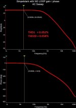
1) Gain and phase of the amplifier with no global loop at all;
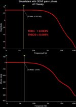
2) Gain and phase of the amplifier with ODNF in place;
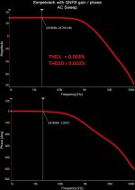
3) Gain and phase of the amplifier with the global NFB (from the output to IPS's sources);
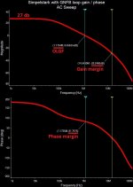
4) Loop gain and phase for the variant (3) with global NFB.
Note that I had to increase the gain of the front-end, so that I can kill that excessive gain with the global loop. I have added only 27db - as a result, that's the loop gain at 1KHz.
Differences between the variants are not really significant, as bandwidth and linearity of the "original" amplifier circuit are rather high. Anyway, those pictures illustrate some key dependencies, I think.
Attachments
I mean - the trimmer, adjusting the ratio of NFB divider, is set to a position where the signal levels at "+" and "-" inputs of the error subtractor are the same so that the error channel contains only an error signal at the output.
Easy to check as minimum RMS at the output of the opamp.
A suspicion:
Replacing D1 and D2, you slightly changed open-loop gain of the main amplifier. Thus, error correction for output stage became sub-optimal with old setting of R32. So, by re-adjusting R32, you improved effective output stage linearity.
If this is not (completely) wrong, one would need a method to better isolate impact of error amplifier on output and input stage.
As last resort, one could perform a simulation with ideal output stage, so that its linearity goes out of the picture. Modification of error amplifier gain would show its impact on distortions caused by input stage.
Cheers,
Matthias
Nice curves. I think it is the feedback loop gain of the ODNF mode that I am also curious about. That is the loop gain of the loop containing the opamps. In the case where the opamps are tuned to output the error only.
Here we go - this is the loop analysis of the error feedback circuit.
The signal source is placed between the output of the amplifier and the feedback divider of the error channel. The input of the amplifier is grounded, so the opamp's output gives us not only the error but also a part of the signal injected. Anyway, the feedback loop analysis seems to be correct.
Attachments
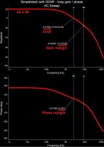
So this shows 18dB of global NFB with 2.6MHz unity gain. That’s modest and within the 20dB rule of thumb for NFB before problems set in. I assume the output is not loaded.
The output is loaded with 8 ohm resistor, but how does it influence the picture? It's important to see that this is not the normal operation of the circuit. In the normal operation, we have the signals in the same phase at both "+" and "-" inputs of the error channel, resulting in the error-only signal in the point of injection. In the above simulation, the input is grounded, so the "+" input of the opamp is grounded as well.
The key point - this 18db loop is applied "locally" to the opamps structure (error channel). The main amplifier "does not see" it. It only gets the correction signal at the level of around -55...58 db, applied at the OPS input (follower), so it's not amplified any further.
I tried the following - in the situation with the "balanced" error subtractor (I see only the error signal at the opamp's output) I made the 2-nd opamp oscillate at around 5 MHz (there is one more local feedback there - I used that one to cause the oscillation). I see that oscillation at the opamp's output. But not at the amplifier's output - it's simply filtered out before it's reaching the amplifier's output. Behavior, very different from the "traditional" global loop situation.
Wait - while I'm writing this, I've got a cool idea to test
")
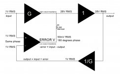
Comparison
You can set 1/B = TRX so the closed loop gain is independent of A but the feedback loop gain is ABX, the same as the conventional system.
OK, in my system X = 1, making the formulas even simpler.
Now, here's the point - overall gain in my system is equal to T.
It's independent of A - that's exactly the condition for ODNF to work properly.
The error channel's loop characteristics, shown in the post #145, practically do not influence the amplifier's overall characteristics - they are strongly canceled-out after all.
If I ground the output of A - nothing happens except the distortion increase, as there's no (-error) injection anymore.
Neither the amplitude nor the phase responses change.
See the diagram attached.
Attachments
The third last line on the sheet seems to agree with results from post #135 and #128.Comparison
You can set 1/B = TRX so the closed loop gain is independent of A but the feedback loop gain is ABX, the same as the conventional system.
Ok. ODNF => 1/B=TRX (X=1 and T= your G and R=5.1k)OK, in my system X = 1, making the formulas even simpler.
Now, here's the point - overall gain in my system is equal to T.
It's independent of A - that's exactly the condition for ODNF to work properly.
No.The error channel's loop characteristics, shown in the post #145, practically do not influence the amplifier's overall characteristics - they are strongly canceled-out after all.
If I ground the output of A - nothing happens except the distortion increase, as there's no (-error) injection anymore.
Neither the amplitude nor the phase responses change.
By your own measurement, the op-amps apply 18dB of NFB at low f. This will cause the op-amps to try to control the output voltage and this certainly will affect the overall characteristics of the amp. Eg: try measuring the output resistance. I also notice in post #142 that the overall unity gain f has doubled or more with ODNF and the phase response slightly straightened.
It is tempting to think that the closer the output voltage tracks the input voltage the less feedback exists. But this isn't so! Feedback affects the sensitivity of the circuit to input/output difference regardless of what that difference is. The feedback is always "fully on".
The absence of change of the overall closed loop gain does not imply there is no feedback. The op-amps are simply using their local excess voltage gain to control the global closed loop gain to be the same as before. Because that's what you have told them to do.
Last edited:
Barring mistakes, the diagrams and the equations should agree.The third last line on the sheet seems to agree with results from post #135 and #128.
That's the way it works
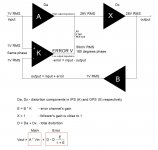
In my particular case E = 18db, however, as 18db / (1+18db) is rather close to 1, it does not influence the overall gain / phase characteristics of the amplifier, as I mentioned earlier.
Once again, the dominant component in the formula is A, so the amplifier's gain, phase and other characteristics are defined by A.
Distortion D is a sum of Da and Dx - so all distortion components are corrected.
E only influences the accuracy of the error correction - the higher E means the lower Error at the output.
ODNF does not really change the "character" of the amplifier evenly decreasing the harmonics amplitude. I see it in my prototype measurements. That's exactly what I like it to do
Attachments
OK.Once again, the dominant component in the formula is A, so the amplifier's gain, phase and other characteristics are defined by A.
Distortion D is a sum of Da and Dx - so all distortion components are corrected.
E only influences the accuracy of the error correction - the higher E means the lower Error at the output.
ODNF does not really change the "character" of the amplifier evenly decreasing the harmonics amplitude. I see it in my prototype measurements. That's exactly what I like it to do
Cheers,
Matthias
By your own measurement, the op-amps apply 18dB of NFB at low f.
No, because of the reason I mentioned - the "+" input of the opamp was grounded for that measurement
. Connecting it to the input makes a big difference, making the real influence looking as 8 / (1 + 8) = 1db (18db = 8 times). This is what I also see in simulation if I connect the "+" input to the signal source.Yes #135 does except that I have treated the IPS as a transconductance amp and my equation includes R. I haven't checked #128.The third last line on the sheet seems to agree with results from post #135 and #128.
No, because of the reason I mentioned - the "+" input of the opamp was grounded for that measurement
Re post #154 diagram
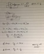
The transfer function is
Vo/Vi = [ (AR + K)X ] / ( 1 + KBX )
The feedback loop gain is KBX.
Can you estimate KBX for your circuit?
Re measuring feedback
You need to connect everything up in the sim as in the proper operation of the circuit. Then insert an ac voltage source (ac=1 dc=0) into the feedback loop. Then measure the ratio of the voltages either side of the voltage source. Do not apply any input signal.
You're trying to consider K as a gain stage. From the overall amplifier's point of view, it's not. It's a small helper, producing the difference between the input signal and attenuated output signal.
The transfer function:
Vo/Vi = AX
And then, we have additional component from the error channel, looking like:
KBX / (1 + KBX)
This additional component sets the rate of distortion cancellation. Nothing else.
Assuming, the amplitudes at the "+" and "-" inputs of the opamp are equal.
The transfer function:
Vo/Vi = AX
And then, we have additional component from the error channel, looking like:
KBX / (1 + KBX)
This additional component sets the rate of distortion cancellation. Nothing else.
Assuming, the amplitudes at the "+" and "-" inputs of the opamp are equal.
- Home
- Amplifiers
- Solid State
- No-global-loop amplification