Thanks Valery,real problem are these bastards,i think that i have all other parts.Thimios, I've got some of those in stock - just need to reach my external warehouse - I will arrange a few pairs for you via post
Is there anything else you're short of for building a pair of those? I will review my stock a bit broader then.
I can't go farther in other IPS that Jeff sent for the same reason.

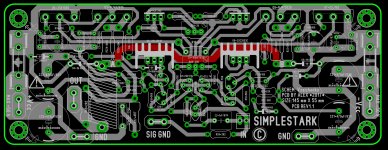
Are you open for modifying layout?
Output inductor directed to the IPS - very bad.
High-current OPS placed inline - bad.
High-current supply inputs provide huge loop - moderate.
Far distance to decoupling caps - moderate.
High-current paths near IPS - bad.
High-current loop around IPS - very bad.
Maybe this one ?
I want to make it diy friendly . Are you agree dual layer it's simpler ? Now, we have, two power ground, and one signal ground .Are you constructive, to layout, a better PCB? Regards,
Alex
Attachments
Last edited:
Maybe this one ?
Try this OPS Layout:

I want to make it diy friendly.
Alex, i really have no doubt in your skills, but let me provide small hint.
The main and alone mission of the amplifier - is to manage supply caps discharging to the load.
[emoji4]
So - as short as possible high-current tracks and as small as possible high-current loops. There are no one reason to place OPS devices in line.
Amp output must be placed near OPS capacitor ground, so the load current can easily flow from supply pin of the cap to the ground pin of the cap. Of course, that path must be short and have small loop area.
Just draw path from one capacitor terminal to other. With placement shown you easily move high-current ground in the OPS area and IPS/VAS could be connected to this ground poly directly far to the left.
Output inductor must be placed as far as possible from board, usually at the output terminals.
Are you agree dual layer it's simpler ?
Yes, of course. Top layer must be fullfilled with ground poly. In modern days we have relatively cheap priduction, so dual layer is the one must-have choice.
Are you constructive, to layout, a better PCB?
Yes, mostly component placement
Last edited:
some people say that the amps with gnfb from the range 15-40dB usual mostly do not sound good...
Yes, I know that, but I just shared my expirience with the real (not simulation) circuit. Without gnfb, amp sounded great, but when I added little bit of loop feedback around the ops, it just sounded better...
I think this is probably just prejudice, it all depends on the topology and the implementation. I have build AB amps with as low as 17dB, as high as 60dB, and my latest two models run at 30dB, slap bang in the middle.
I really think it depends on the design, and how you organise the linearity. And of course not every person hears the same sound, either. Purists generally love zero distortion amps, and this mandates very high global fb, but many tube loves like a low global feedback amp because it reminds them of their tube amps.
I found the profile of the harmonics very important. H2>H3>H3>H4>H5 needs to almost a straight line.
HD
Generally speaking, you are more likely to get a musically satisfying amp by having as little feedback as possible and instead concentrating on linearity, unless you are a feedback expert. Feedback is not a free lunch. Start there and then add feedback and see how the sound changes.
ODNF
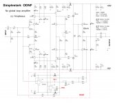
As the most of distortion is coming from the OPS, I thought - why don't I try ODNF (Only Distortion Negative Feedback) around the OPS.
Here is a simple addition to the previous circuit - OpAmp U3 subtracts a portion of the output signal from the input signal, U4 amplifiers the inverted error signal and "mixes" it in at OPS input, modulating the transimpedance stage's load reference.
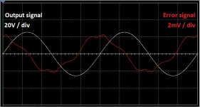
As a result - overall level of distortion is reduced for about 10 times.
You can see the error signal - red curve at picture 2.
Output impedance is also roughly 10 times lower.
Hugh - I fully agree, it very much depends on overall design, OPS architecture, etc. - many nuances, influencing the sound clarity.
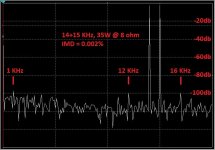
This one is a fully symmetric topology, so even harmonics are strongly suppressed, at 1KHz, 3 and 5 are the tallest ones (although at 20KHz, 2 and 5 are the tallest ones). Anyway, taking in account all the components above 5 are noticeably lower, there's no "ringing" - I expect it to sound pretty cool.
I'm going to test both variants - with and without ODNF - it's easy to switch it off, simply shorting TP2 to ground (although slight offset trimming will be required).
Cheers,
Valery
As the most of distortion is coming from the OPS, I thought - why don't I try ODNF (Only Distortion Negative Feedback) around the OPS.
Here is a simple addition to the previous circuit - OpAmp U3 subtracts a portion of the output signal from the input signal, U4 amplifiers the inverted error signal and "mixes" it in at OPS input, modulating the transimpedance stage's load reference.
As a result - overall level of distortion is reduced for about 10 times.
You can see the error signal - red curve at picture 2.
Output impedance is also roughly 10 times lower.
Hugh - I fully agree, it very much depends on overall design, OPS architecture, etc. - many nuances, influencing the sound clarity.
This one is a fully symmetric topology, so even harmonics are strongly suppressed, at 1KHz, 3 and 5 are the tallest ones (although at 20KHz, 2 and 5 are the tallest ones). Anyway, taking in account all the components above 5 are noticeably lower, there's no "ringing" - I expect it to sound pretty cool.
I'm going to test both variants - with and without ODNF - it's easy to switch it off, simply shorting TP2 to ground (although slight offset trimming will be required).
Cheers,
Valery
Attachments
As the most of distortion is coming from the OPS, I thought - why don't I try ODNF (Only Distortion Negative Feedback) around the OPS.
Here is a simple addition to the previous circuit - OpAmp U3 subtracts a portion of the output signal from the input signal, U4 amplifiers the inverted error signal and "mixes" it in at OPS input, modulating the transimpedance stage's load reference.
As a result - overall level of distortion is reduced for about 10 times.
You can see the error signal - red curve at picture 2.
Output impedance is also roughly 10 times lower.
Hugh - I fully agree, it very much depends on overall design, OPS architecture, etc. - many nuances, influencing the sound clarity.
This one is a fully symmetric topology, so even harmonics are strongly suppressed, at 1KHz, 3 and 5 are the tallest ones (although at 20KHz, 2 and 5 are the tallest ones). Anyway, taking in account all the components above 5 are noticeably lower, there's no "ringing" - I expect it to sound pretty cool.
I'm going to test both variants - with and without ODNF - it's easy to switch it off, simply shorting TP2 to ground (although slight offset trimming will be required).
Cheers,
Valery
I did some simulation on ODNF amps. Maybe you could find useful staff in this thread. ODNF or no GNFB power amp
BR Damir
I did some simulation on ODNF amps. Maybe you could find useful staff in this thread. ODNF or no GNFB power amp
BR Damir
Damir, thank you for the link - interesting to see the challenges you went through. Using too high ODNF loop gain may result in instability at HF - same as with any kind of feedback. That's why I consider 20db enough for the purpose. Even in this case I have to use a very little bit of lead compensation (C10) for phase correction. Another important thing - opamps must be fast
It seems to me you are trying to add a second transconductance stage with global NFB based on op-amps. Are you assuming that op-amps will sound better than your original stage would with GNFB?
I agree with bogdan_borko except that I don't think you have avoided GNFB at all, you have just avoided including your original transconductance stage in the loop.
I like your ingenuity but I can't help thinking you will get a better real-life result by following your original intention to avoid GNFB and by simplifying your circuit and making it as linear as you can.
Last edited:
Member
Joined 2009
Paid Member
I read all the internet sites and generally found myself drawn to descriptions of amplifiers with no-feedback. Easily done with tubes but harder with transistors. Nevertheless, the no-feedback advocates won my heart - they always write so passionately that once you find their websites you feel as if you know where the gold is hidden that everyone else has missed. I devoured this information, parts choices, topology preferences, all the tricks and insider knowledge for those who believe. There is some kind of mythology in place that creates an excitement and a desire to become a fully signed up member. And I really wanted to believe. I built tube amps with no feedback and a variety of SS feedback amps with different feedback levels.
Alas, the best sounding amplifier to my ears is SS with gobs of global feedback, including significant local feedback around the OPS.
I haven't given up the dream yet, I do have a no-feedback discrete SS amp (not even local loops, only degeneration) designed, which also has Diamond output, and the pcb's are in hand for a few months but no time to build yet!
Last edited:
And since ODNF is global NFB I may have to report you for being off-topic in your own thread.
Why do you consider ODNF in my configuration being "global"?
Its loop covers only OPS - pre-drivers and drivers (unity gain buffer) - taking the input signal as a reference.
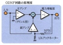
Same approach as Luxman uses in a series of amplifiers - see the picture attached. The feedback loop is local.
Error correction in OPS from the post #22 can be also considered as a "only distortion local feedback" around OPS, taking the reference "clean" signal from the intermediate unity gain buffer - only error in OPS is corrected.
The other approach, used by Nakamichi, for example - is CFP configuration of the OPS. Complementary FEEDBACK pair - feedback is embedded by design there, but it's local again. I've got a few well-behaving OPS configurations with this approach as well (including one with BJTs/HexFETs combination), although CFP requires very careful design for keeping it stable - internal loop gain is high enough for parasitic local oscillations.
It would be possible to arrange a global ODNF loop, if I would feed the input jFET's sources - which doesn't make sense, that's why I don't do it
So - no global loops in Simplestark ODNF
It's just an error correction approach for the OPS.Attachments
I read all the internet sites and generally found myself drawn to descriptions of amplifiers with no-feedback. Easily done with tubes but harder with transistors. Nevertheless, the no-feedback advocates won my heart - they always write so passionately that once you find their websites you feel as if you know where the gold is hidden that everyone else has missed. I devoured this information, parts choices, topology preferences, all the tricks and insider knowledge for those who believe. There is some kind of mythology in place that creates an excitement and a desire to become a fully signed up member. And I really wanted to believe. I built tube amps with no feedback and a variety of SS feedback amps with different feedback levels.
Alas, the best sounding amplifier to my ears is SS with gobs of global feedback, including significant local feedback around the OPS.
I haven't given up the dream yet, I do have a no-feedback discrete SS amp (not even local loops, only degeneration) designed, which also has Diamond output, and the pcb's are in hand for a few months but no time to build yet!
Hi Gareth,
I don't really believe in "myths" around one design technique or the other
Working in the area of low-distortion circuits during some time, I can arrange a voltage gain stage, with any reasonable gain, sticking to "degeneration" local loops only - current drive approach, some high-precision current subtraction / mirroring techniques and right impedance matching provide very high linearity with no global loop in place.
However, OPS is a different story. Two key characteristics - higher currents and slower semis - make it special. As a result - approaches that I consider as suitable ones for keeping the distortion low enough for good audio:
- Lateral MOSFETs at the output - cool, but selection of available devices is getting more and more narrow over the time;
- Non-switching arrangements, particularly addressing the crossover region (I don't consider true class A in SS as practically useful due to its horrible energy efficiency);
- Error correction in OPS - one way or the other. CFP is also in this group.
Balanced OPS designs, including circlotrons - may provide additional distortion components compensation.
Those are the things I'm trying to explore these days
Cheers,
Valery
Last edited:
Your op-amp subtracts amplifier input from output and feeds that into the forward path. That is what GNFB is.Why do you consider ODNF in my configuration being "global"?
You have paralleled the original input stage with an opamp.
Local NFB around the OPS would not take its input from the amplifier input.
Arguments about what is and what is not abound in this technology, but the result is important. Regard the ergocentric fellows going on about current fb v. voltage fb. It is just ideology, and semantics, the important aspect is whether it is better or worse for SQ.
Even if we arrive at a better mousetrap, there will always be disagreements about whether it is better or worse...... the only option is to present it all to 100 listeners in a double blind test and then do the stats. And if the sample is less than 10k individuals there will still be heated disagreements. Fact is audio is like food. Some like chilli, some like sugar, some like bitter.
Meanwhile engineers will design and build legions of them and the market will make its slow, corrupt decisions over many decades. Ho hum.......
Valery, I think your concept does compare input to output, albeit with an intervening opamp, and then passes the error signal to the forward path, as Bryan has said. Dammit, the guy is right, and it does define as NGFB - but heck, it's uniquely done, and I congratulation you for trying something different. This stuff was all known well more than fifty years ago but you, and other smart guys like you, are still devising different mousetraps.....
Bravo...... NGFB or no, bravo. And having had a mild stroke years ago which corrupted my speech area, I am lost in admiration for Valery's command of both the technology and the elegant descriptions in his (presumably?) second language.
Now, consider replacing your opamp with a tube... have you thought of that?
Hugh
Last edited:
Your op-amp subtracts amplifier input from output and feeds that into the forward path. That is what GNFB is.
You have paralleled the original input stage with an opamp.
Local NFB around the OPS would not take its input from the amplifier input.
OK, let's look at it from a different point of view.
Even though ODNF error detection circuit takes the input signal as a reference, the whole front-end (voltage amplification) part of the amplifier still works open-loop. There is no global loop around it whatsoever. It does not know anything about error correction, happening right behind it. Correct? Correct.
Error signal is injected at the driver stage's input, being subtracted from the signal, coming from the front-end's (high swing) output. Then this signal, with error subtracted, goes through the OPS, that adds the error back to it, compensating the "minus error", that's already there, leaving "virtually no error" signal at the output. Error compensation is not 100%, mostly due to limited ODNF loop gain, set by the designer - as we understand, higher ODNF loop gain will lead to higher error compensation effect, but lower loop stability at the same time - same as any feedback loop.
Once again - the front-end is out of the loop completely. Agree?
Now - one more thing. I can change ODNF loop gain in a wide range of values - it does not influence the overall amplifier's gain at all. It only sets to what extent the error is going to be corrected.
Very different behavior, comparing to the "classic" global negative feedback.
Distortion in the error "detection" and amplification path is negligible - fast, highly linear opamps deal with much smaller signals, than the main voltage gain circuit.
Overall amplifier's behavior - no global loop with -20db error correction.
As nice side effects - slightly wider bandwidth and 10 times lower output impedance - both are purely because of ODNF loop, affecting purely OPS operation.
BTW, I used opamps just for simplicity and "transparency" of the circuit - error correction thing may be arranges with discrete components easily.
- Home
- Amplifiers
- Solid State
- No-global-loop amplification