Damir, as always good and helpfull work.
Thank you also for this usefull information.
Could you please, share the simulation file?
Thank you.
Of course.
Attachments
Schematic in post #62 in my opinion use same strange resistor values and very low OPS question current. Attached my simulation. There is quite high crossover distortion and very low input impedance.
Damir
")
-RNM
Last edited:
Just by decreasing values for R14 and R16 from 680k (very strange high value) to 47k shows much better results, but still very low input impedance not suitable for some preamps.
By the way, parallel capacitor(C14) to feedback resistor is not recommended in CFA.
Damir
Hi Damir, thank you ... I had 47k, it was working better but when I disconnected output (left it open) than oscillation was here (in simulation), it is why I ended with such strange resistors
...when CCS is used (as in post #72), than current into inputs can be higher and no oscillation is here ... I attached schematic with CCS, you can try it ...
Attachments
... There is quite high crossover distortion ...
Damir
when you set R1/2 to lower value?
Hi Damir, thank you ...
your values are definitely very good, I overlooked, it is stable ... my fault sorry

I want to suggest that the constant curret source for very fast should be adjustible, it should be adjusted untill the input has zero mv, I tried a simulation, and if both ccs have small offset there is voltage at input.
The gain of the amp has to do with the porpotion of input stage vs voltage gain stage bias current, if we say the vas stage is biased at 1mA and the input stage is biased at 1000 times less than the vas, effectivly the current mirrors the input current and effectily gives the input stage a gain of 1000, increacing gain increacses nfb and more nfb means better sound.
I strongly belive the only way to put nfb on your input bc550 bc560 is to have the output some how connected back to either the base or emitter of your input bc550/560, I argue that because you have no connection there isn't any nfb and this input stage would be very high in distortion, I suggest the circuit simulator is wrong, because its impossible for a non nfb stage to be this linear. Unless theres a thd measurement done in real life proving this or a proper explnation on why its fed back.
The collector of the transistor is not a input and it will not amplify a signal when connected to collector.
I revisited the schematic once more and yes you are right it's not cascoded. because the base of the q3 q4 is not connected any where to ground, it has a high impedance to ground.
The open loop gain of 55db is pretty small, I lately designed high gain amps about 230db of gain, it always sounds better with more feedback, unlike how some articles says too much feedback reduce sound quality.
The gain of the amp has to do with the porpotion of input stage vs voltage gain stage bias current, if we say the vas stage is biased at 1mA and the input stage is biased at 1000 times less than the vas, effectivly the current mirrors the input current and effectily gives the input stage a gain of 1000, increacing gain increacses nfb and more nfb means better sound.
Thanks for your explanation.You have to put more effort to understand this amp. Input contains so called supper pairs (Boxall supper pair, sometime wrongly called Baxandall supper pair), it looks similar to the diamond buffer here. The 169R resistor (R19) is a part of NFB together with 470R (R12), and no cascode in the input, just in its output and in the output buffer.
This preamp use about 45 dB of GNFB and open loop gain (about 55 dB) is defined by ratio (R48/R19)*(R5/R15). I hope it will help you.
Don't be surprised with very low distortion.
I strongly belive the only way to put nfb on your input bc550 bc560 is to have the output some how connected back to either the base or emitter of your input bc550/560, I argue that because you have no connection there isn't any nfb and this input stage would be very high in distortion, I suggest the circuit simulator is wrong, because its impossible for a non nfb stage to be this linear. Unless theres a thd measurement done in real life proving this or a proper explnation on why its fed back.
The collector of the transistor is not a input and it will not amplify a signal when connected to collector.
I revisited the schematic once more and yes you are right it's not cascoded. because the base of the q3 q4 is not connected any where to ground, it has a high impedance to ground.
The open loop gain of 55db is pretty small, I lately designed high gain amps about 230db of gain, it always sounds better with more feedback, unlike how some articles says too much feedback reduce sound quality.
Last edited:
I suggest the circuit simulator is wrong, because its impossible for a non nfb stage to be this linear.
You probably want to rethink this. Think about how circuit simulators work; they cannot be 'wrong' but you can feed them wrong info.
Jan
Humans are not perfect and they do not know everything..
You could try a little harder and at least read the numbers correctly - 500 kHz square wave signal on my measurement pictures.
You could try a little harder and at least read the numbers correctly - 500 kHz square wave signal on my measurement pictures.
Firstly, I couldn't see any 500khz square picture on the link you gave me.
Secondly, I can only find 201khz test square on your first page.
It looks you don't want to see what is obvious, a big number on a signal generator which clearly express 500 kHz. I did not post a link to first page, read post #73 carefully again.
Anyway 500 kHz square wave output signal speaks for itself (250 ns time base) and on second pic 32,8 Vpp / 1MHz on 10 Ohm load resistor, which gives more than 12 Wrms at 1 MHz.
Anyway 500 kHz square wave output signal speaks for itself (250 ns time base) and on second pic 32,8 Vpp / 1MHz on 10 Ohm load resistor, which gives more than 12 Wrms at 1 MHz.
Attachments
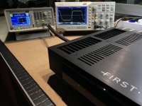
For me is more important the slewrate and the rise / fall time (10%-90%) at full voltage swing.
How it's look the square signal îs the second part.
If the amplifier îs stabile than the square will look ok.
I think this is important not only for you but for everyone. Square waves tells a lot more. It's the package of all possible measurements to which amp should be tested and of course, final approval is listening test.
Anyway 500 kHz square wave output signal speaks for itself (250 ns time base)
http://www.diyaudio.com/forums/solid-state/312596-fast-cfa-concept-9.html#post5248598
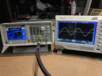
even in simulation and with ccs improvement is not so fast square as yours

... i must working harder, but I am closer ...
Attachments
Last edited:
It looks you don't want to see what is obvious, a big number on a signal generator which clearly express 500 kHz. I did not post a link to first page, read post #73 carefully again.
Anyway 500 kHz square wave output signal speaks for itself (250 ns time base) and on second pic 32,8 Vpp / 1MHz on 10 Ohm load resistor, which gives more than 12 Wrms at 1 MHz.
Your link sent me to #7xx a tripple digit number.
Your 500khz square is at #73 two digit number.
My exprience from testing, square wave response can be totally irellavant to the sound quality.
I tried a good schematic amp and I made it oscillate on purpourse by not giving it pF compensation, it still sounded better than the other refrence amp that does perfect square waves at 20khz
- Status
- This old topic is closed. If you want to reopen this topic, contact a moderator using the "Report Post" button.
- Home
- Amplifiers
- Solid State
- Another very fast CFA concept