I built this original circuit on a dot matrix board, mono around 1981-82. Very easy on the ears. Will be happy to build again with modern transistors if PCB is developed.
Hello Sir, Can you remember the sonics? Was it similar to JLH69 as claimed? I am in the preparation phase for doing it on a dot board, I intend to use 2n3904,2n3906,BD439, TIP3055 and TIP2955. As you said, a PCB will make things easier.. May be Prasi, our forum member who is known for his quick PCB designs, could lend a helping hand
Hello Sir, Can you remember the sonics? Was it similar to JLH69 as claimed? I am in the preparation phase for doing it on a dot board, I intend to use 2n3904,2n3906,BD439, TIP3055 and TIP2955. As you said, a PCB will make things easier.. May be Prasi, our forum member who is known for his quick PCB designs, could lend a helping hand
I had at that time a stereo JLLH class A 69 circuit assembled in stereo. The hum level of classA was more than the class AB. I used both to hear music. I personally preferred the Class AB.
Electronics corporation was manufacturing P & N channel power transistors in TO3 case. I used them and 2n3054 in the amp.
Please see this thread also. JLLH 20watt Class AB Lateral Mod
Hello Sir, Can you remember the sonics? Was it similar to JLH69 as claimed? I am in the preparation phase for doing it on a dot board, I intend to use 2n3904,2n3906,BD439, TIP3055 and TIP2955. As at woyou said, a PCB will make things easier.. May be Prasi, our forum member who is known for his quick PCB designs, could lend a helping hand
I could not recommend the use of TIP3055 and TIP2955 as the unity gain (value 1) frequency is around 3MHz whereas the MJL3281 and MJL1302 reach unity gain at 30 MHz.
As gain declines phase increases and so the outset of this can be pushed to a much higher frequency with the MJL's allowing more nfb to be used to reduce distortion.
You don't need to worry about that with TIP's in a Class A amplifier as the devices do not turn off as they do in a Class AB. For these you need something faster to make up for switching time delays at the crossover point.
There is an inverse relationship between time and frequency which results in the lower unity gain frequency because of these switching delays.
In the direct coupled circuits I have posted I replaced the bootstrap collector load for the Vas transistor (2N3904) with a constant current source.
There is more information about the JLH1970AB at The Class-A Amplifier Site - JLH Class-AB Amplifier
It well may be the results on hardware demonstrated there to be no audible difference between this circuit in comparison to the 1969 Class A and that simulations are just that.
I came to a dead end with the simulation for the JLH1970AB. The results were not much different from other Class AB designs unless the standing current was increased to about 70% of that for my existing 1996 Class A amplifier which I have continued to use for that reason.
There is an option for those interested in the JLH1970AB comparing Class AB with Class A operation by means of switch to adjust the standing current for each operating mode.
Dissipation of heat requires large heat sinks for Class A operating - it would be possible to incorporate a normally open thermostat to short out one of two series bias resistors to reduce the bias down to Class AB level if needed in summer conditions.
With +/- 24volt supply rails I recommend using BC546B and BC556B instead of 2N3906 and 2N3904 which should be restricted to +/-18volt supply rails due to 40volt Vce their rating maxima.
The MJL3281 and MJL1302 have higher current gain as well as higher frequency response and the saturation voltages are lower which allows operation with lower supply rails. If chosen correctly there can be no loss of output power compared to other transistor types.
I am tidying up a simulation of a direct coupled version of the 1970AB and will post this later.
There's not much point in questioning past history. The events, beliefs and tastes of 50 years ago are irrelevant now, except to those who can recall them. The sound quality of typical, small class AB amplifiers of the day was actually quite poor and the opportunity in 1969 to build a cheap and very simple class A amplifier, was obviously very attractive for a wide range of DIYs....Why has this circuit, not gained much popularity?
Simply, the combination of class A in an ingenious, minimal and cheap circuit, was a winner. Class AB in a more complex arrangement just wasn't attractive. I suspect that it's curiosity about the past that now leads us to reconsider these forgotten ideas.

Many thanks for the replies. Can I request a simulation of the original bootstrapped singlerail circuit please? Also, is 2SC5200 and 1943 pair a good op device for this topology?
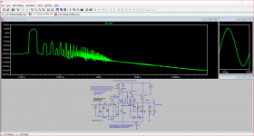
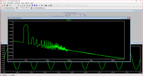
The answer to both questions is yes time has been short so this has to be piece meal. Images 3 and 4 are at 15W rms and 1W rms at 1kHz respectively into 8R. The FFT's look much better. A lot of listening is done at levels of 1W and there is a body of thought that the First Watt is the most important one.
I will post the simulation file tomorrow. I have used the .models for the outputs due to Cordell and provided a link to his site. The remainder come from the SPICE library.
Attachments
Original JLH1970AB modified for dc coupled output
Note the previous thumbnails refer to the version with the CCS collector load on the voltage amplifer.
The split rail version of the original now attached differs in having a bootstrap collector load. (The original was single rail, output capacitor coupled - the details can be seen in a link posted recently by me)
I have included the .commands for 1k and 20k. Using these is a matter of clicking that required for testing and changing the status from comment to SPICE directive.
In addition the test frequency and voltage input need to be changed in V1.
Also click on .tran 400u and change the time to 8 m for 1kHz. The start times for these tests should be 200u and 4m respectively.
The set up if for Class AB operation. For Class A tests the link that shorts R10 needs to be removed using the big hand "Move" tool.
I have changed back to 2N3906 and 2N3904 transistors since these do not have the base connection open - Linsley-Hood indicated these were suitable in his original articles.
The series output resistor 0.22R is an addition Hood included in his later designs - I have left this as an option. This approach can be seen also in Naim power amplifiers.
The purpose is to give a small buffer to work against delayed signals from loudspeakers getting into the nfb loop.
Attachments
Open the .asc file. Right click your mouse on the screen and from the drop down menu left click to select run. Move the mouse to touch the vout label and a red probe will appear.
Left click when that happens - this opens the .raw file. Right click on the screen and move the mouse to select the option to view.
Right click to see the options for error log or FFT and left click from the drop down box enter 200uS for the start time and click OK. The same procedure applies to view the error log.
There is a battery of test simulations you can investigate from CordellAudio.com - Tutorial Simulations of which this is merely one example.
Member
Joined 2009
Paid Member
There's not much point in questioning past history. The events, beliefs and tastes of 50 years ago are irrelevant now, except to those who can recall them. The sound quality of typical, small class AB amplifiers of the day was actually quite poor and the opportunity in 1969 to build a cheap and very simple class A amplifier, was obviously very attractive for a wide range of DIYs.
Simply, the combination of class A in an ingenious, minimal and cheap circuit, was a winner. Class AB in a more complex arrangement just wasn't attractive. I suspect that it's curiosity about the past that now leads us to reconsider these forgotten ideas.
I think a lot of those earlier AB designs when built today with modern parts playing into modern speakers sound pretty darn good, afterall, the AKSA 55 design did very well for Hugh and is of this heritage
True, but then Hugh's amplifier designs are not really simple at all. They are all modified, tweaked etc. to achieve a specific, audiophile quality sound, essentially based on harmonic distortion profiles. If you were now to build and listen to original 8-20 Watt amplifiers following say, Mullard/Philips, EMI etc. circuits from the 1960-70 period, you wouldn't be quite so enthusiastic about their sound quality - it really wasn't good compared to what could still be achieved then with tubes and most likely prompted JLH and others to DIY something sounding better according to audition rather than measurements in his case.
The engineering way is to simply eliminate distortion altogether - right down to ppb level if you follow the examples in laboratory amplifier threads here. It's just less satisfying building such large and expensive amps when squeezing the most satisfying sound possible from a handful of cheap parts can be so much easier, more rewarding and fun")
The engineering way is to simply eliminate distortion altogether - right down to ppb level if you follow the examples in laboratory amplifier threads here. It's just less satisfying building such large and expensive amps when squeezing the most satisfying sound possible from a handful of cheap parts can be so much easier, more rewarding and fun
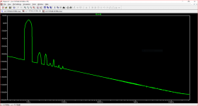
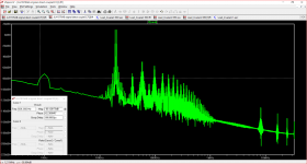
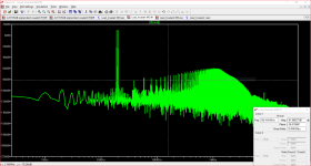
I looked at the IMD for the JLH1970 and compared this to a Blameless at close to 1W rms into 8R out into 8R with 19kHz+19kHz input.
In the attached images the horizontal cursor has been placed as close as possible to -80 dB to compare the old with something a decade or so later.
In the attached images the horizontal cursor has been placed as close as possible to -80 dB to compare the old with something a decade or so later.
Attachments
The Rega Brio seems to be based on this JLH circuit.
Rega Research Brio integrated amplifier | Stereophile.com
Rega Research Brio integrated amplifier | Stereophile.com
thanks.
interesting.
all i can say is ...
wow!
mlloyd1
interesting.
all i can say is ...
wow!
mlloyd1
I looked at the IMD for the JLH1970 and compared this to a Blameless at close to 1W rms into 8R out into 8R with 19kHz+19kHz input.
In the attached images the horizontal cursor has been placed as close as possible to -80 dB to compare the old with something a decade or so later.
very interesting !! thanksThe Rega Brio seems to be based on this JLH circuit.
Rega Research Brio integrated amplifier | Stereophile.com
Rega Brio
I owned a Rega Brio amplifier for a short time. The main issue for me was that it did not have a remote control. I have seen the structure of circuit on which this was based - it is not due to Linsley-Hood.
very interesting !! thanks
I owned a Rega Brio amplifier for a short time. The main issue for me was that it did not have a remote control. I have seen the structure of circuit on which this was based - it is not due to Linsley-Hood.
- Status
- This old topic is closed. If you want to reopen this topic, contact a moderator using the "Report Post" button.
- Home
- Amplifiers
- Solid State
- Simple Class AB - Linsley-Hood 1970