Yes this is based on the original single rail a NP camp amp which is copywrited.
So no schematics just replace the 2SK170 with a BC337-40 which is a 1amp device for a reason. To ultimately drive a parallel pair of S
2SK1161s, operating off a 24 volt switching supply. Then I can reduce the value of the emitter resistor.
The CUP fan can be driven via a 7812for less noise and that can be bolted to the chassis. I solder an 0805 SMD 1uF cap between pins 2 and 3. The ZTX450, which is part of the constant current circuit can also be replaced by a BC337-40.
I'm confused. I thought this was the DLH thread but you are saying you simply mod the ACA JFET input with a BJT and it becomes a single rail DLH?! Totally different topology isn't it? I don't think it's a problem to link ACA schematic from ACA thread. However, I want to make sure we are taking about DLH variants here and not ACA variants so we don't clog up this thread with non-DLH stuff.
Side by side now.
Please show me how ACA-cum-DLH....
Side by side now.
Please show me how ACA-cum-DLH....
Last edited:
Please do not detract from the original thread. The ACA already has a specific thread, so any changes to it must be exposed in its thread. If you want to convert the ACA to DLH, you must share the schemas with the modifications that are mentioned (as was clearly done in this thread). Otherwise, I will ask the moderators to move the posts that do not correspond to the thread.
regards
regards
Good now we are on the same page.
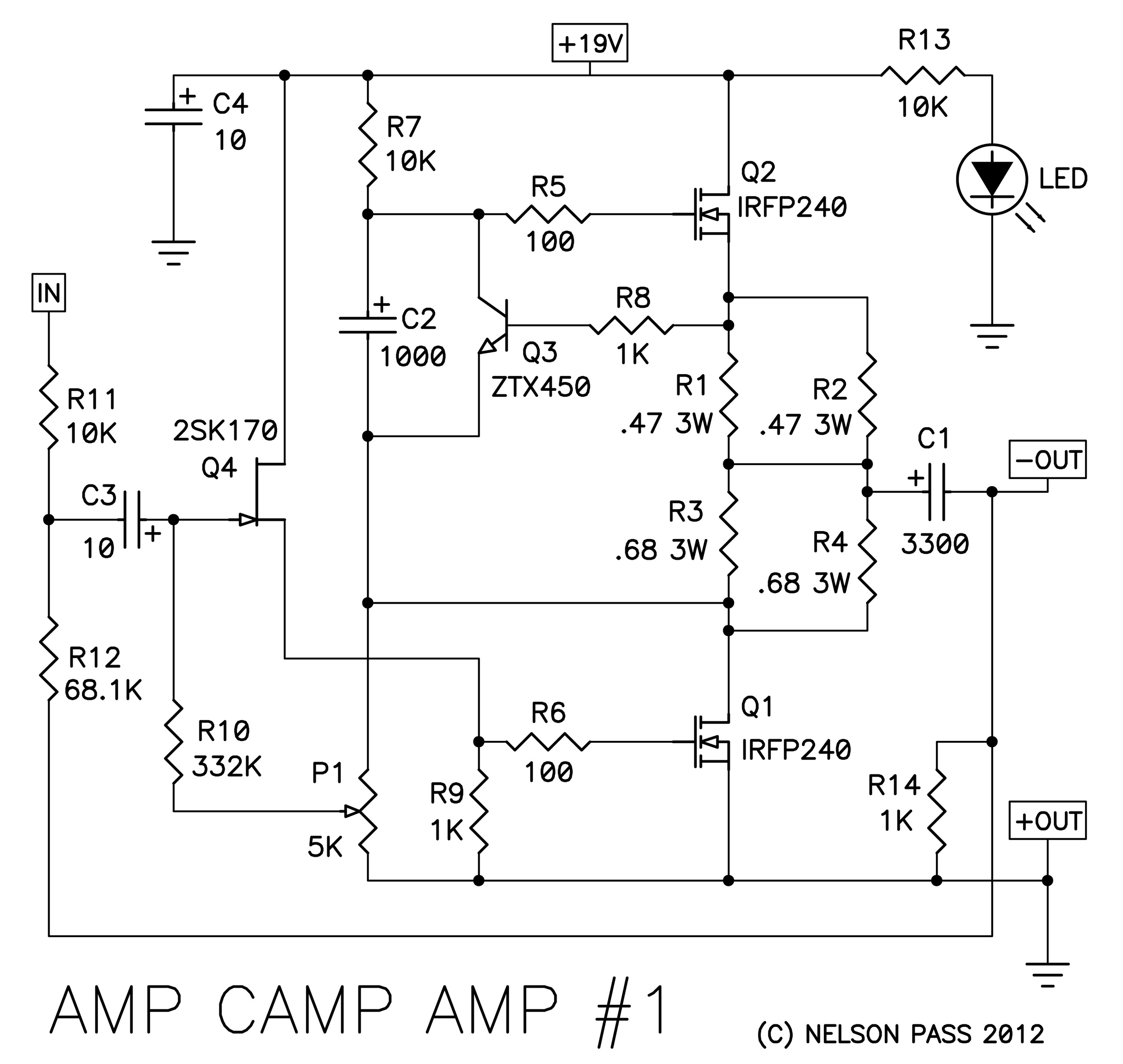
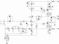
Camp Amp #1.
Which is a single rail amplifier. Excuse me as I am new on the forum and all my schematics are in Pdf format.
Replace Q4 and Q3 with BC337-40.
Q1 and Q2 with 2SK1161 available on eBay.
Change P1 to 10K
R1+R2=0.22 Ohm 5W
R3+R4=0.22 " "
R3+R4=0.22
Are the only modifications required.
Camp Amp #1.
Which is a single rail amplifier. Excuse me as I am new on the forum and all my schematics are in Pdf format.
Replace Q4 and Q3 with BC337-40.
Q1 and Q2 with 2SK1161 available on eBay.
Change P1 to 10K
R1+R2=0.22 Ohm 5W
R3+R4=0.22 " "
R3+R4=0.22
Are the only modifications required.
Very simple version tested with great success.
Hi Horacio,
Is this the final version of the amp?
regards
Prasi
Hi Horacio,
Is this the final version of the amp?
regards
Prasi
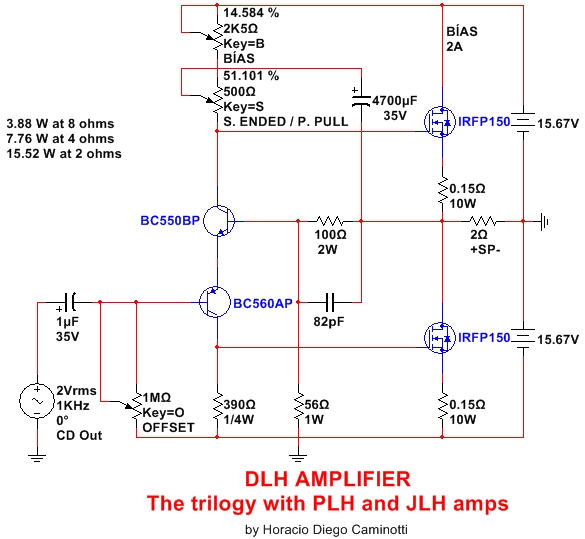
Hello Prasi, that is a very simple version that you can build and works excellently well. It requires alternating adjustments between the bias and the offset, until reaching the optimum point at the final operating temperature. It is not strictly necessary to filter the ripple noises that could be introduced into the base of the BC560C through the 1M trimpot. I have tried it with 28200 uF per rail and no hum or hiss, even with sensitive speakers. The sound quality is amazing. I do not think there are many amplifiers that can overcome it and, if they do, they reach it with circuits that are much more complex and more expensive. The quality specifications of the DLH are incredible.
You can also mount the one that has been successfully tested by xrk971.
The option of the first post works just as well, although the offset is more variable with the temperature than the other versions.
The DLH is not a very flexible circuit to the changes, except for the base polarization of the BC560C. These different ways of polarizing the base of the BC560C give life to different versions (some with advantages over others). The inflexibility to the changes responds more to maintain the parameters of original quality, to avoid designs with poor or mediocres specifications.
regards
Last edited:
Hi Horacio,
Thank you very much for your kind answer.
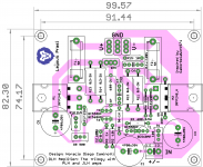
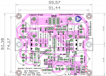
Here is my version of layout based on Gabor and xrk's layout.
Questions:
1. Do you think we should separate input and power ground and may be lift it by 10R +anti parallel diodes.?
2. Also would it be prudent to incorporate power diodes from supply to speaker o/p .
3. zobel ckt included in layout. is it ok?
4. Would inductor be necessary on PCB OR speaker terminals?
One more thing, although the layout is very much diy friendly, people can utilize the on-going offer at easyeda of 2USD for 10 PCB + shipping")
regards
Prasi
Thank you very much for your kind answer.
Here is my version of layout based on Gabor and xrk's layout.
Questions:
1. Do you think we should separate input and power ground and may be lift it by 10R +anti parallel diodes.?
2. Also would it be prudent to incorporate power diodes from supply to speaker o/p .
3. zobel ckt included in layout. is it ok?
4. Would inductor be necessary on PCB OR speaker terminals?
One more thing, although the layout is very much diy friendly, people can utilize the on-going offer at easyeda of 2USD for 10 PCB + shipping
regards
Prasi
Attachments
I do not know whether any of your proposals will be necessary.
But I strongly advise you to incorporate the PCB pads and traces to allow all those to be added if you find any are beneficial/required.
5. and maybe also at the power tappings for the front end. Low capacitance X7R here.
I would put the output inductor (with it's damping resistor) into the cable running to the output terminals so that is is located away from the PCB and away from metal panels.
Last edited:
Very nice layout Prasi. Thanks so much for a professional layout for all of us!
You have room for input rail bypass caps - certainly never hurts. Low ESR ceramic or 100nF film cap bypass would be good as well. I don't think double source resistors needed. Single 3W is fine in my experience and testing.
Also, maybe add parallel path for film bypass on input cap. Probably 4.7uF square box cap enough.
Thanks!
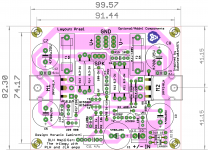
ok... here is a layout with optional/additional components (that were not in the original sch) marked in red.
I reckon, since I have space, better to use double source resistors, may be for 2ohm load?
I reckon, since I have space, better to use double source resistors, may be for 2ohm load?
Attachments
Last edited:
Day by day you do it better.ok... here is a layout with optional/additional components (that were not in the original sch) marked in red.
I reckon, since I have space, better to use double source resistors, may be for 2ohm load?

Hello Eric,
the 4700 uf cap was included in the first post by the designer. So thats why I kept it too. anyway there is a parallel film cap so that could be used as well instead of the 4700uF or both could be used. there was some explanation by designer somewhere in the thread, although, honestly, i didnt read it carefully enough.
regards
Prasi
edit here it is
DLH Amplifier: The trilogy with PLH and JLH amps
Last edited:
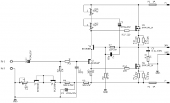
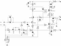
Well here's another pcb. I definitely recommend Prasi's pcb as it has all of the extra parts for really tweaking up the amp. I already had this done just in case someone was looking for the final, simple version. The power mosfets are as wide as I could get them and still stay in the 100mm or less size break at the manufacturer.
Attachments
Its done!
hint: for those who use board houses.....sometimes the PCB manufacturer goes ahead manufactures single sided boards as single sided. Its better to instruct specifically to them to manufacture double sided boards. That way you will have nice solder mask on both sides (blue or red or black) + you will have pads on top side too.. helps with measurements.
edit: added pdf files for etching. all views from component side.
Attachments
Last edited:
Hello Diego,
first, Thanks for this simple design!!
I want to build this amp but I have no experience with amps..
I have some questions:
-How to set bias? I measure + power line with an amp meter in series while I turn pot VR10?
-Regarding mode SE or PP, the pot VR9 should stay either max to one side either to the other side, or it can be in-between?
-If I have different voltage PS, let's say 18V or 22V, should I change values to some parts?
Thanks,
Daniel
- Home
- Amplifiers
- Solid State
- DLH Amplifier: The trilogy with PLH and JLH amps