Have the 4 big electrolytics on the top been changed? Depending on amount of use, 30 years of ripple could have them in a pretty sorry state.
That being said, the Wima polyester bypass caps underneath look like current production so I can't imagine them being 30 years old. And it seems like good odds that the 'lytics were changed out at the same time the Wimas were put in....
That being said, the Wima polyester bypass caps underneath look like current production so I can't imagine them being 30 years old. And it seems like good odds that the 'lytics were changed out at the same time the Wimas were put in....
No, Farflunger. Maybe we can see what he's got in the PSU section. Since you were talking about adding L and may more C to his power supply.Hello,
Are you talking to me?
Yes, I built a Hiraga amp with a toroidal transformer. I took a lot of crap for that one.

Farflunger,
In general, the fault for poor soundstage, separation, et al is the use of a single power supply for both stereo channels. The fix is either to use two supplies or replace the existing output capacitor(s) with units having much larger values and higher voltage ratings. This can get expensive, bulky and inconvenient, unfortunately. Some example values: 2200/4700uF@60V replace with 10,000uF (or double that!) at the same or higher voltage. The overall philosophy is that caps store energy and a surge (drain) in one channel should not affect the other channel. Higher-voltage caps than the supply mean that the caps are under-stressed. Good Luck!
In general, the fault for poor soundstage, separation, et al is the use of a single power supply for both stereo channels. The fix is either to use two supplies or replace the existing output capacitor(s) with units having much larger values and higher voltage ratings. This can get expensive, bulky and inconvenient, unfortunately. Some example values: 2200/4700uF@60V replace with 10,000uF (or double that!) at the same or higher voltage. The overall philosophy is that caps store energy and a surge (drain) in one channel should not affect the other channel. Higher-voltage caps than the supply mean that the caps are under-stressed. Good Luck!
Hello,
The caps in the original design were bigger. I mean much bigger than usual in those days.
The caps used in the amp from the original poster are probably 1000000µF 40 volts.
Changing this amp into double mono would imply a new chassis. I would go for choke input like the one i described before.
Now having a 100000µF right after the rectifier is giving the transformer and the rectifier a hard life. I could well imagine adding a 33000µF cap after that a choke and putting the two present caps in parallel would already give a nice improvement.
greetings, Eduard
Farflunger,
In general, the fault for poor soundstage, separation, et al is the use of a single power supply for both stereo channels. The fix is either to use two supplies or replace the existing output capacitor(s) with units having much larger values and higher voltage ratings. This can get expensive, bulky and inconvenient, unfortunately. Some example values: 2200/4700uF@60V replace with 10,000uF (or double that!) at the same or higher voltage. The overall philosophy is that caps store energy and a surge (drain) in one channel should not affect the other channel. Higher-voltage caps than the supply mean that the caps are under-stressed. Good Luck!
This man speaks the truth.
I have found that unless all of the components in the chain from source to loudspeakers are "dual mono" you have no idea how spacious stereo can sound.
It is not a subtle difference.
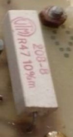
Ugrade modification can be new 0.47R source power resistors.
Big 12 watts Mills MRA12 easy to do
Mills MRA-12 Resistors
With this your sound stage , voices and acoustic instrument timbral content be nice natural.
Non-inductive version of wire wound have less Johnson noise is very quiet and sound transparent
Big 12 watts Mills MRA12 easy to do
Mills MRA-12 Resistors
With this your sound stage , voices and acoustic instrument timbral content be nice natural.
Non-inductive version of wire wound have less Johnson noise is very quiet and sound transparent
Attachments
Ugrade modification can be new 0.47R source power resistors.
Big 12 watts Mills MRA12 easy to do
Mills MRA-12 Resistors
With this your sound stage , voices and acoustic instrument timbral content be nice natural.
Non-inductive version of wire wound have less Johnson noise is very quiet and sound transparent
Hello,
At the time i did built Hiraga amps ills were not available. I did however use wirewound resistors that were constructed the same way Mills are.
So the original poster did get some ideas to improve his amp.
BUT there are not many Hiraga amps with choke input power supply!!
Greetings, Eduard
@ EduardBUT there are not many Hiraga amps with choke input power supply!!
Greetings, Eduard
Sure choke input psu that is excellent upgrade
Just more complicated to make them correctly.
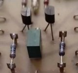
Little trimmer with vertical on the top viper for offset
easy position regulation that simple to do.
Greetings
Attachments
Hello
Little trimmer with vertical on the top viper for offset
easy position regulation that simple to do.
???
If You use ll2733 lundahl and you have around 24 volts dc on the first cap you should have 24 divided by 100 mH ( LL2733 inductance with two coils in parallel) = 240mA bleeder current. So you should put a 100 ohm BIG resistor across the first cap that comes after the choke. Sone one in the negative and one in the positive part of the supply.
NOW people will tell you. This a class A amp there will always be a current running no need for the two 100 ohm resistor. But better be safe than sorry i would say.
OF COURSE you will need a transformer with a higher secundairy voltage. So for the same VA rating you will get less current because of the higher voltage.
But the transformer will work better with choke input so no need to worry about that.
Greetings, Eduard
Little trimmer with vertical on the top viper for offset easy position regulation that simple to do.
???
What i see is very tricky acrobatic to regulate output offset with horizontal viper position of the trimmer.

Attachments
Hello,
Recently i met a good friend for whom i built a Hiraga amp in the past ( 25 years ago) He had it checked by a famous audio technician who told him that he can modify it in such a way that it would become even more musical at the expensive of a reduced output power. My friend will keep me informed. Greetings, Eduard
Recently i met a good friend for whom i built a Hiraga amp in the past ( 25 years ago) He had it checked by a famous audio technician who told him that he can modify it in such a way that it would become even more musical at the expensive of a reduced output power. My friend will keep me informed. Greetings, Eduard
I use Shuguan black treasure series tubes and PSVane tubes. I think the Carys need a service to be honest. Surprised £10k of amps are being beaten by the Hiraga.
I like shugaung too, shugaung 12ax7-t is my best pre amp tube.
I'd say theres no way your going to get siginifcant sound quality improvements. Unless you are a guru and you can mod or creat a new schematic from scratch.
Chaning transistors to hifi new high performance transistors would help. But diffrence noticible? Not allot.
Measure your output dc voltage if its more than 1mV when fully warmed up then having a multi turn pot to adjust dc voltage would improve sound quality. And again improvment but insignificant.
Other than that I'll keep the amp original.
Currently in picture it seems like already multi tun, you can adjust to absolute zero. However becaue its very old 30 years. once you turn it may well mean the pot break down too old and amp may become damage or destructed.
http://www.ti.com/lit/ds/symlink/lm431.pdf
You can replace your orignal zener diode with a lm431. Oridanary zener diodes are very noisy.
Last edited:
Hello,
Recently i met a good friend for whom i built a Hiraga amp in the past ( 25 years ago) He had it checked by a famous audio technician who told him that he can modify it in such a way that it would become even more musical at the expensive of a reduced output power. My friend will keep me informed. Greetings, Eduard
Actually last week I met a 'famous technician' and he told me he was working on a Hiraga. Must be the same amp. He told me in technical terms what he did to it. Guys name is PvW?
Jan
Hello Jan,
You are right. There were some little changes made like diodes, poer cable. BUT the big '' redesign '' has not been done yet as far as i know.
My friend told me the power output will drop from 20 to 10 watt so it will be a BIG change.
I am sure if the change has been made i will be the first one to know.
Greetings, Eduard
P.s Peter told him the Hiraga is still one of the best solid state amps even tough it has been there for decades
So I have a Hiraga, it's over 30 years old and may well have been an original build by Hiraga or created by another for Expolinear speakers - it's branded Expolinear and i was told was used to demo their speakers back in the day.
It sounds very very good, beating my big Cary valve amps in almost every area except soundstage. To fix this id like to try changing some components but as there are so many different schematics out there I have no idea which applies to my amp. So, if I take some pics could someone point me in the right direction?
Adey
Hi!
If you don't already have the schematics drawm for you amplifier, I can do it for you if you send 2 close-up pictures of the PCB - top and bottom.
I guess it will be quite close to the original Hiraga schematic like this:

Good luck!
Hello,
The original poster did stop to post in this thread . The Hiraga amp is still a VERY nice one.
The kits available now use different transistors, cheap resistors ( the original one uses Shinkoh tantal ones) .
Most of the money for the original 20 and 30 watt Hiraga amps was in the power supply.
No cheap toriodal transformer but double C. The ones i built used CLC supply instead of CRC after the French start using CLC in other solid state class A designs.
The caps used where well known brands chosen for their specs and sonic qualities which are kind of related.
Today lots of amps are constructed using low grade caps from ebay. There arent that many manufactures of quality caps. AND most commercial gear uses cheap parts because they want you to buy something new within a decade. I mean 5 years.
Greetings, Eduard
P.s most of the info on Hiraga is on the net. Even scans of the original publications in French but illegal to copy and paste into this site.
I've designed Class A amp +-24v zero emitter and collector +base resistor plus 3 pairs outputs ocl and idle at 2.3-2.6Amps per supply rail with big cooling, very cheap 24v 4A switch mode power supply was used per channel and worked well。Hello,
The original poster did stop to post in this thread . The Hiraga amp is still a VERY nice one.
The kits available now use different transistors, cheap resistors ( the original one uses Shinkoh tantal ones) .
Most of the money for the original 20 and 30 watt Hiraga amps was in the power supply.
No cheap toriodal transformer but double C. The ones i built used CLC supply instead of CRC after the French start using CLC in other solid state class A designs.
The caps used where well known brands chosen for their specs and sonic qualities which are kind of related.
Today lots of amps are constructed using low grade caps from ebay. There arent that many manufactures of quality caps. AND most commercial gear uses cheap parts because they want you to buy something new within a decade. I mean 5 years.
Greetings, Eduard
P.s most of the info on Hiraga is on the net. Even scans of the original publications in French but illegal to copy and paste into this site.
EDIT: did I mension SMPS short circuit protection? This meant I had few circuit errors during design and build, no fuses or bulbs required, power up and short protect no components damaged. Normall supply no portection blow up very scary. Have not tried short output when music playing, but amp should be blow out proof when dc detrection relay is also used.
Last edited:
Hello,
The original poster did stop to post in this thread . The Hiraga amp is still a VERY nice one.
The kits available now use different transistors, cheap resistors ( the original one uses Shinkoh tantal ones) .
Most of the money for the original 20 and 30 watt Hiraga amps was in the power supply.
No cheap toriodal transformer but double C. The ones i built used CLC supply instead of CRC after the French start using CLC in other solid state class A designs.
The caps used where well known brands chosen for their specs and sonic qualities which are kind of related.
Today lots of amps are constructed using low grade caps from ebay. There arent that many manufactures of quality caps. AND most commercial gear uses cheap parts because they want you to buy something new within a decade. I mean 5 years.
Greetings, Eduard
P.s most of the info on Hiraga is on the net. Even scans of the original publications in French but illegal to copy and paste into this site.
Sorry I didn't know that. Actually I thought Hiragas schematics were "public domain" by now. Since they were published in magazines all over the world...
Anyway, is there any way I can edit my post? I find no <edit> button.
Here is the schematic made for myself, since I have a couple of half finished, modified 20W class A PCBs that were based on this amp. Note that the transistors are not the ones I will use, they were available in the program I used at that time. Now I use KiCAD which is free and quite useful!
Close to the original:

The mod I wanted to try:

Simple simulation:

Layout:

So far:

Any comments?
Last edited:
- Status
- This old topic is closed. If you want to reopen this topic, contact a moderator using the "Report Post" button.
- Home
- Amplifiers
- Solid State
- Idiot seeks help with Hiraga