Another possible cause of the problem is the power supply fuses may have blown from the incident. Check those and that the AFE board is getting the +/-60v power supply. Bill.
Power supply supplying power to the rails of the AFE and through to the OPS as well. Although I did encounter that very issue earlier. Modern 6x30 fuses are just that teensy bit smaller than the 3AG 1/4 inch of the past. Had to needle-nose crimp the fuse holders tighter. I'll re-verify when I test again.
...First, with IPS set at 2ma, was the VAS current in the appropriate range per the testing procedure? Second, did you remember to move the H1 jumper back to the normal setting before proceeding to adjust the OPS bias?
H1 jumper in the operating position. AFE front end is operating properly, with current readings as per instructions through R12/R13, proper relative drive voltages + and - from AFE to OPS. OPS V+ and V- getting their ~60V. OPS grounded. Connections are tight.
Thank you for this explanation.Concerning acceptable range for the OPS bias, the targeted 40mv is equal to 400ma total bias current as measured across the OPS 0.1 ohm resistor. This is equivalent to 200ma across each MOSFET pair. This is considered pretty healthy (high) bias to minimize crossover distortion and will make the heat sinks run warmer. A more typical bias current is where the MOSFET thermal coefficient is zero which is normally between 100-150ma bias per MOSFET pair or 200-300 ma total bias for the two pair per channel. MOSFETs do required a certain minimum bias current for proper switching operation and to minimize crossover distortion. I don’t know exactly what that is but I wouldn’t go below say 50ma per pair. Certainly the MOSFETs won’t operate properly at near zero bias current.
If the problem is not as simple as forgetting to move the H1 jumper back after setting the IPS/VAS currents, I would start checking for bad solder joints from VR2 forward. Also check that the wires between the AFE and OPS boards are securely connected. Good luck, Bill.
I'm going to do the old mechanic's trick, swapping known good for suspected bad. I'll put the other channel's AFE on the bad channel's OPS and see if I get the same crazy DC offset and signal shift. If so, it's somewhere in the relatively simple OPS. I like that. Fewer parts.
And on to more hours of disconnecting, connecting, test & measurement setups. After I paint the house and try to plug a car tire that got a puncture and ride the motorcycle on this gorgeous weekend!
Here's a neat thing:
I don't have a signal generator, so I've got a YouTube 1k sin wave 10 hour long video into a preamp into the amp. Use the measure on the scope and set the volume to get the appropriate voltage amplitude and off we go!
Power supply supplying power to the rails of the AFE and through to the OPS as well. Although I did encounter that very issue earlier. Modern 6x30 fuses are just that teensy bit smaller than the 3AG 1/4 inch of the past. Had to needle-nose crimp the fuse holders tighter. I'll re-verify when I test again.
H1 jumper in the operating position. AFE front end is operating properly, with current readings as per instructions through R12/R13, proper relative drive voltages + and - from AFE to OPS. OPS V+ and V- getting their ~60V. OPS grounded. Connections are tight.
Thank you for this explanation.
Start with the amp ruuning normally with no signa.
Check the rail voltages at the output transistort drains.
Measure the voltages at Vrive + and Vdrive -.
Assuming that the output voltage is zero, V+ drive should be in the range of +0.3 to +1.0 volt. Same for V- drive, but opposite polarity.
Even before doing this, it is useful to check the AFE in the test mode where the jumper is to TP1.
Cheers,
Bob
I'm going to do the old mechanic's trick, swapping known good for suspected bad. I'll put the other channel's AFE on the bad channel's OPS and see if I get the same crazy DC offset and signal shift. If so, it's somewhere in the relatively simple OPS. I like that. Fewer parts.
And on to more hours of disconnecting, connecting, test & measurement setups. After I paint the house and try to plug a car tire that got a puncture and ride the motorcycle on this gorgeous weekend!
Here's a neat thing:
I don't have a signal generator, so I've got a YouTube 1k sin wave 10 hour long video into a preamp into the amp. Use the measure on the scope and set the volume to get the appropriate voltage amplitude and off we go!
I swapped the AFE sides, and it let me bring the VR2 current up on the board in question, and the OPS side in question was happy with the already up VR2 current.
So I sat and watched two happy sin waves on the scope for fifteen minutes, tweaked the VR2 up to ~38 mV and put the bench speakers on. I'm halfway through Level 42's World Machine, the heatsinks are at about 188 degrees f and the VR2 measurements are holding steady with no DC offset.
I'm going to go with DH500Fan's observation of a connection not tight enough. Simplest explanation is probably the most likely. Tomorrow I'll give all boards another physical and visual solder inspection, put the wings back on the turkey, take it downstairs, and enjoy some music.
Sorry for the false alarm. I'm sure I'll be back within a week with a different issue the burn in reveals.
Bob, Level 42 never sounded so good on these cheapie in-wall speakers.
Hey Dennis. Glad to hear you got your amp running. You mentioned the heat sink temperature is running 188F. That’s very toasty and considered too hot for the long term reliability of the amp. The 188F is equivalent to 87C. The thermal breakers mounted on the heat sink should shut down the amp over 70C so it sounds like there is a problem with them. It could be as simple as fresh thermal paste needs to be applied under the breakers or the breakers themselves don’t function. You can pull and test them. The breakers should be closed and have continuity across the terminals below 70C (158F) and open above that temp. I’ve tested them in the oven by heating them up slowly and measuring continuity to determine when they open. Breakers typically have not aged very well over 30+ years of operation. Luckily you can get replacements for the two breakers for $12.95 on EBay.
To get the amp to run cooler, reduce the bias setting. The Hafler DH220 service manual suggests a bias of 275ma (their method of measuring the bias also includes the current to the front-end board so is equivalent to about 230ma bias to the MOSFETs). Try reducing the bias to 250-300ma which hopefully will reduce the heat sink temps to a reasonable range of say 40-60C (e.g., something less than the thermal breaker setting of 70C with margin so the amp won’t shut down in normal operation). Bill.
To get the amp to run cooler, reduce the bias setting. The Hafler DH220 service manual suggests a bias of 275ma (their method of measuring the bias also includes the current to the front-end board so is equivalent to about 230ma bias to the MOSFETs). Try reducing the bias to 250-300ma which hopefully will reduce the heat sink temps to a reasonable range of say 40-60C (e.g., something less than the thermal breaker setting of 70C with margin so the amp won’t shut down in normal operation). Bill.
Last edited:
Breakers typically have not aged very well over 30+ years of operation. Luckily you can get replacements for the two breakers for $12.95 on EBay.
You're not going to believe this.
I put the wings back on the turkey today and got a ground hum. I turned it off, went outside, and painted the house for a few hours.
One dim bulb test later, flicking the power on, I saw a little spark from the right channel's breaker.
Fantasia 'preciates muh business.
 Ordered new ones.
I could just hard-wire that right side in the mean time if I act as my own personal thermal breaker with my laser temperature gun, couldn't I?
...ducks...
Ground hum issue sorted.
Running for about an hour through the test bench (okay, folding table in my home-office) speakers.
Van Morrison 's No Guru, No Method, No Teacher played through as warm up; halfway through Monk's Straight- No Chaser.
Heat sinks around 118; Vr2 idle voltage at ~38mV.
I will hook up to the real system tonight and enjoy a cocktail.
These are available directly from Linear Systems (linearsystems.com). However, it is best to obtain them from Rick when you buy the boards, since a bit of pre-selection between the LSK489 and LSJ689 is very desirable. The amount and direction of their input offset voltages should be similar. See the discussion on my web page at cordellaudio.com.
Cheers,
Bob
Cheers,
Bob
a 200 series something
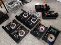
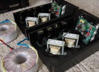
While repurposing a bunch of parts, I was being tormented by my mind and imagination. When arranging parts... chassis, transformers, capacitors, capacitor banks, wiring harnesses, driver PCB, power modules and heatsinks. A comprehensive array of things lay before me.
My task to think of [sensible, LOLS] linear approaches to building, sort of in tiers... price, power ranges, operating voltage ranges... overall complexity. Things I am building for myself to keep, some strictly to experiment and model ideas... a handful to sell to close friends, who track and follow closely what I do.
I am also trying not to be afraid of trying some far reaching things, many I have only endlessly pondered... ~ what ifs ~
Laugh if you will, this amp is 80% done... is be(coming) something.
I will be a BIG AMP KILLER. Stay tuned...
Attachments
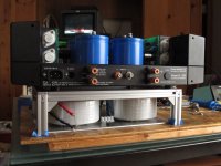
200 series with 82 volt rail
This 82 volt powered amp sound fantastic! Exicons are still breaking in...
The essence of my P-230 mono amp concept is one of experimenting and trying things. Frankly, they were never meant to be permanent, it was not good to "become attached" to particular builds... conversely it is always good to know when the particular piece of equipment is JUST RIGHT, should be left alone, from further work.
I have 4 chassis's deemed as P-230 monos (not as bridged amps!) And now add to that, the top covers... 8 possible amp builds. The amp(s) with Mundorf MLytic HC, are hard to equal... there is something very special about their sound. For now, the 3 mono amps that have the Mundorf HCs are my standing reference... I am working to "EQUAL" them. The principle negative to Mundorf LOCOs, they are expensive, huge and a challenge to stuff into a box.
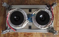
I had 4 banks of caps (8 100v - 8 80v) using the Jensen 4-pole 100v and combined with a 58v / 600va toroid which I combined with PA-7 / Exicon (singles) on an open chassis for maximum dissipation. These amps are remarkable. and should be. using good parts.
Image 2 Version(s) 2 - 3 - 4 Who really knows??
(the other bank of Jensens) which I am planning to eventually build a CLC supply. I have laid out the chassis pan(s), where I can do it in stages [to listen and make notes] I eventually can "move the toroid below" = get all of the AC power out of the box...
The Jensen 4-pole caps that have been a focal point in upgrade path over the years, with the cessation of production... it has been necessary to look at every option. These Slim cap(s) profile makes for easy (easier) placement in builds. The PS-200 P/S board also has many possible uses... including building an CRC or CLC is very easy... OR separate front end / and output stage supplies.
This 82 volt powered amp sound fantastic! Exicons are still breaking in...
The essence of my P-230 mono amp concept is one of experimenting and trying things. Frankly, they were never meant to be permanent, it was not good to "become attached" to particular builds... conversely it is always good to know when the particular piece of equipment is JUST RIGHT, should be left alone, from further work.
I have 4 chassis's deemed as P-230 monos (not as bridged amps!) And now add to that, the top covers... 8 possible amp builds. The amp(s) with Mundorf MLytic HC, are hard to equal... there is something very special about their sound. For now, the 3 mono amps that have the Mundorf HCs are my standing reference... I am working to "EQUAL" them. The principle negative to Mundorf LOCOs, they are expensive, huge and a challenge to stuff into a box.
I had 4 banks of caps (8 100v - 8 80v) using the Jensen 4-pole 100v and combined with a 58v / 600va toroid which I combined with PA-7 / Exicon (singles) on an open chassis for maximum dissipation. These amps are remarkable. and should be. using good parts.
Image 2 Version(s) 2 - 3 - 4 Who really knows??
(the other bank of Jensens) which I am planning to eventually build a CLC supply. I have laid out the chassis pan(s), where I can do it in stages [to listen and make notes] I eventually can "move the toroid below" = get all of the AC power out of the box...
The Jensen 4-pole caps that have been a focal point in upgrade path over the years, with the cessation of production... it has been necessary to look at every option. These Slim cap(s) profile makes for easy (easier) placement in builds. The PS-200 P/S board also has many possible uses... including building an CRC or CLC is very easy... OR separate front end / and output stage supplies.
Attachments
What's that??Exicons are still breaking in...
I understand you're referring to your power devices. As any semiconductors, they can be regarded as best when they're brand new, still fulfilling their datasheet specs. So, »breaking in« means degeneration??
Best regards!
~ y e s ~
OK?? I grasp that. Been under the hood for over 45 years...
I (have been) enjoying ~ 40 year old vintage Hitachi MOSFETS
which have very ~ s l o w l y ~ degenerated away over time.
These poor dying Exicons will outlast most of us,
I think I am OK. I am loving this ~ break in ~
with a gentle evolution in beauty.
What's that??
So, »breaking in« means degeneration??
OK?? I grasp that. Been under the hood for over 45 years...
I (have been) enjoying ~ 40 year old vintage Hitachi MOSFETS
which have very ~ s l o w l y ~ degenerated away over time.
These poor dying Exicons will outlast most of us,
I think I am OK. I am loving this ~ break in ~
with a gentle evolution in beauty.
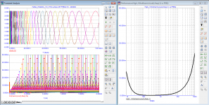
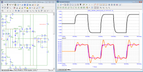
Typed Amp Model Hafler HD-220C
removed the Bode diagram and loop gain without capacitor C2
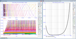
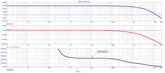
measured the dependence of THD on frequency at 1 W and 40 V (peak) at a load of 8 ohms (4-period)
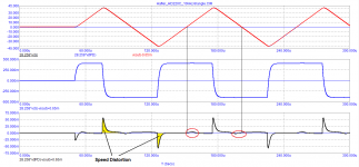
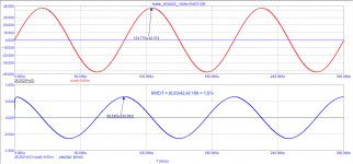
did the SWDT Haffler test (amplifier fails the test)
measured speed distortion, they are very large! 0.14%
removed the Bode diagram and loop gain without capacitor C2
measured the dependence of THD on frequency at 1 W and 40 V (peak) at a load of 8 ohms (4-period)
did the SWDT Haffler test (amplifier fails the test)
measured speed distortion, they are very large! 0.14%
Attachments
-
 Hafler_DH-220C_Speed Distortion.png27.8 KB · Views: 144
 -
 Hafler_DH-220C_10kHz-SWDT.png28.1 KB · Views: 100
 -
 Hafler_DH-220C_THD-vs-freq.png106.6 KB · Views: 89
 -
 Hafler_DH-220C_1W_THD-vs-freq.png88.3 KB · Views: 89
 -
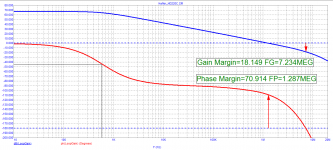 Hafler_DH-220C_Loop-Gain.png28.7 KB · Views: 87
 -
 Hafler_DH-220C_Bode.png20.2 KB · Views: 185
 -
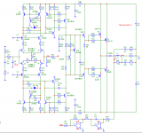 Hafler_DH-220C_SCH.png30.7 KB · Views: 205
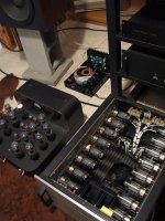
Playing alongside the .really big. dogs ;
It is remarkable that these "vintage" Half'ler / Lateral MOSFET based amps are "at home" with other very lofty BEHEMOTH power amps, vacuum tubes or solid state. I liked the true scale of this image, 8 little amps would fit into the VT200 chassis. It is not a simple, camera lens... perspective sort of thing.
I have "taken heat" for devoting so much time over many years to working with "these old amps", some question why. Personally, for me finessing a design or circuit is a challenge and at a point, even surpassing aspects of much favored performance attributes of the most noteworthy gear, the reward and lesson for the effort. A close friend (after a few listening sessions) quit bringing his Spectral amp over. Up to a point some people do not tend to take serious DIY, or consider approaches taken to equal the most expensive gear that money can buy, or that they can afford.
~ So few people outside of "our group" of dedicated DIY builders ~ really grasp how great these amps are [or can be] my friend with Spectral gear honestly is [indirectly] snooty at times. He will not accept it. **BTW, I love Spectral, the sound, the rich legacy... and would love ~ to be able to afford ~ an all Spectral system. I digress, but .am not. talking down this remarkable company, or their products.
My standing favorite vacuum tube gear is Atma-Sphere (over the past 25 years) serving as a reference in my home. The vintage Half'lers have been my daily drivers for nearly 40 years... and they keep getting better. Harmonically = timbrelly, a well-built "tuned and voiced" amp can indeed share the sound of thermionic gear. Many would/will/do argue this. I own both, what do I care??
I especially like this time of year (with cooler weather) in a ~60 degree basement/shop with tile floors, all amps run cool... I can [reasonably] raise the bias up without concerns of overheating. Time (is the season) to fire up the vacuum tube gear. I have not at this point, A - B'd the current build amps shown, most of the Exicon amps are still burning in... and getting better.
~ KEEP UP THE VALIANT EFFORT Y'ALL ~
we are making a difference in the field
of sheer musical enjoyment,
and a few pocket books.
Attachments
Typed Amp Model Hafler HD-220C
removed the Bode diagram and loop gain without capacitor C2
measured the dependence of THD on frequency at 1 W and 40 V (peak) at a load of 8 ohms (4-period)
did the SWDT Haffler test (amplifier fails the test)
measured speed distortion, they are very large! 0.14%
Hi petr,
Are all of these graphs from simulation, or have you build and measured the DH-220C?
What is your criteria for an amplifier failing the Hafler SWDT (straight wire with gain)?
What is "speed distortion" and how did you measure it?
Cheers,
Bob
- Home
- Amplifiers
- Solid State
- Hafler DH-200/220 Mods