DH 500 Amp
Chris:
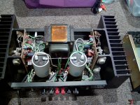
If this amp has been modified by Musical Concepts the only thing that is still original is the main chassis , the transistor heat sink assembly and the protection board . Everything else has been changed , the circuit boards , the large capacitors , the rectifiers and the power transformers and all the input and output connectors. This amp is actually two separate amps on the same chassis , power supplies and everything else . According to Musical Concepts this amp also has much better specs in addition to the increased power output as I mentioned in my first message.
Ed
Chris:
If this amp has been modified by Musical Concepts the only thing that is still original is the main chassis , the transistor heat sink assembly and the protection board . Everything else has been changed , the circuit boards , the large capacitors , the rectifiers and the power transformers and all the input and output connectors. This amp is actually two separate amps on the same chassis , power supplies and everything else . According to Musical Concepts this amp also has much better specs in addition to the increased power output as I mentioned in my first message.
Ed
Hi Ed,
Yes, I'm also very familiar with their work and claims.
I would actually test that amplifier to spec. and see what the truth is before doing anything. You have to know where you are before you can start a journey with undefined targets.
Let me just say that I had to rewire and redesign the grounds on a Musical Concepts pair of amps. This was their product from the ground up. The grounding was pretty poor. The inputs not matched and a few other things. When I was done, noise was down 30 dB!! The customer was pretty blown away by the difference.
Not only that, but they mounted the filter caps upside down by their terminals! You never, ever do that. They finally learned and these days mount capacitors properly they say. Also did a preamp that they made the PCB from a nice Rogers Teflon. The PCB was a mess and the circuit used didn't match the PCB design at all. They deleted the output driver transistors and ran everything stinking hot. It had two external supplies big enough to run amplifiers. When I was done, it ran on one supply (still big enough to run an amplifier). The transistors were changed to a type that could handle the power, and I dropped the standing current a bit. The end result was a much quieter preamp with lower distortion. Their preamp was the same as the original DH-101 minus the outputs and no tone controls. The customer was delighted, and I did provide him with spectrum of the before and after performance. He was then able to sell all that equipment and moved substantially upward. I had nothing to do with his choice, but he ended up with a Marantz 3250 preamp and a pair of 170DC amplifiers. I worked those over as well and today he is extremely happy. Of course had he gone with the original preamp and a couple Hafler amplifiers he would have also been substantially ahead conically. I would have rebuilt those too. But these other units would be rebuilt to original spec, no changes in grounding, just matching transistors.
I'm not selling anything, nor doing a hatchet job on them. I am only reporting what was found and what the corrective measures were. So do test that amplifier and consider the results before doing anything further. Define your targets before wasting any time or energy. What would be best is an Audio Precision test set, or a new RTX-6001 (which is what I'm using). A spectrum Analyzer would work, or a new Keysight U8901A or B. Any of those will show you the truth.
Best, Chris
Hi:
This looks like a DH 500 modified by Musical Concepts .
I have one like this and Musical Concepts rated this amp at about 350 Watts per channel.
Contact Musical Concepts / Musical Design Home for more info.
If not please let me know and I will dispose of this amp for your safety , just send it to me for disposal.
Hope this helps
Ed
njvet01@yahoo.com
Hi Ed,
Thanks for this information. The boards appear to be the stock boards, but some components on the board have been changed, (caps). So this would have been the power supply upgrade with some kind of "enhancement" of the stock board.
Ron
So I finally got the DH-500 with the highly modded power supply and the upgraded board components up and running. I only needed to replace the power switch and it works just fine. DC offset is low, less than 20mV on either side.
It sounds very good--compared to my AT1505 (by ATI). It has a fuller midrange. The highs sound (similarly) clear and detailed, but the bass is more defined.
I admit I don't have a whole slough of awesome amps to compare it to, but I do have my Marantz 6012, which was my starting point, and then I have several DH-200s and an XL280. It sounds better than anything I listened to so far.
I plan to add a soft start so as to keep the switch in good shape. Also, it seems from reading some threads here that removing the thermistor out of the circuit after startup should improve bass response. This totally makes sense to me--the thermistor has very low impedance at high current flow, but once the amp has started the current flow can be pretty low (quiet passages, etc.). In this case the thermistor will be substantially cooler, and its resistance higher, so that you effectively have a choke on your power supply. Am I missing anything here?
I have a set a Qua-Co boards which I am currently populating and will soon compare to the upgraded PC-10b in this unit. I am very interested as to how it will compare.
By the way, does anybody know if it is feasible to use a PC-10 board in a DH200? Since the PC-10 evolved from the PC-6 it seems it should be doable with a few resistor changes. Has anyone done this, or considered doing this before.
Of course I'm really waiting for the Cordell PCB's to be released so I can try that, but until then I will do with what I have.
Thanks for any comments or corrections to my understanding of things.
Ron
Hi guys, I did hear from Bob Cordell and he has been looking at the DH-220C pcb design I did up, now that we have BC-1 design rung out, so progress is being made, a bit at a time, one thing at a time ")
I could offer out the DH-220C design as it stands but if there are changes to be made, design wise, I do not think you would be happy that you got a proto with issues. If there are changes, value changes would be no big deal but a layout change not so.
I wonder how ticknpop made out on using them in his Perreaux?
Last edited:
Hi guys, I did hear from Bob Cordell and he has been looking at the DH-220C pcb design I did up, now that we have BC-1 design rung out, so progress is being made, a bit at a time, one thing at a time
I could offer out the DH-220C design as it stands but if there are changes to be made, design wise, I do not think you would be happy that you got a proto with issues. If there are changes, value changes would be no big deal but a layout change not so.
I wonder how ticknpop made out on using them in his Perreaux?
Is it correct to assume that making this board (once completed) work in a DH200 or a DH500 won't be too formidable of a task?
Wait and see when I get the customer feedback reports
Soldering up the pcb is a bit of a task as it is packed in their pretty tight. Bob did not like all the lead forming of the 2n5551,5401, but that is the only way I could get them to fit with the TO-18 style lead pattern in the IPS.
Any of these projects require previous experience, I would not suggest this as a first time project.
My prototype was easier (wiring to the fets) to assemble than putting it into a Hafler, since the pcb is so close to the bottom the terminal blocks will not work very well, thus solder the wires in like they did originally, saves $ but not as pretty.
Last edited:
While the details of the Cordell board are still being worked out, I have some questions regarding some mods done previously.
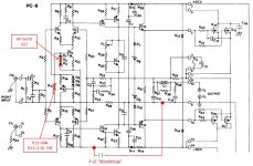
I picked up a DH200 on EBay which sounds really good. Several mods have been performed on it, including the addition of quite a few "Wondercaps". A couple of the changes I found are illustrated in the attached JPG. They replaced D1,D2 and D3 with a simple LED (HP 6678). This goes between the base of Q3 and the negative rail. The LED glows brightly when the circuit is powered. And related to this (I think) they replaced R11 39k resistor with a 2.2k 5W resistor between the base of Q3 and the ground. What would be the effect of this modification on the circuit, and how might it make it sound better? They made similar changes to the components at the base of Q4, though these are not shown on the attached schematic.
They also added 4uF "Wondercaps" between ground and the positive and negative rails.
Thanks for any insight offered.
Ron
Attachments
R11/R13 decreased value is simply to properly bias the LED that replaces the small diodes. Although 2.2kohm generates a high current so the LED must be selected accordingly. Led is good for voltage reference thus stable bias current in the input stage but I am not sure on the level of contribution on the sound...
The added 4uf surely provides additional front stage power supply filtering. Are you sure these are the only mods? Maybe updated old electrolytic caps or else....
Fab
The added 4uf surely provides additional front stage power supply filtering. Are you sure these are the only mods? Maybe updated old electrolytic caps or else....
Fab
Last edited:
Are you sure these are the only mods? Maybe updated old electrolytic caps or else....Fab
For sure there are more additions of capacitors, and yes the electrolytics have been updated--they are now Elna, and C5 value has been switched from 470uF to 100uF.
There have been added 0.33uF Wondercaps between the drain and ground of Q14/Q15 and Q16/Q17.
There has been added a 0.1uF Wondercap in parallel with C5 (feedback capacitor?)
But strangely C1 appears to be stock. And the power supply is stock.
That's all I can see right off the bat, but there appears also to be some kind of wiring changes related to the fusing. I will try to figure that out next.
I don't know which of these changes made the largest difference, but this amp sounds much much better than the stock DH200's I have on hand (I have a couple of them).
Ron
R11/R13 decreased value is simply to properly bias the LED that replaces the small diodes. Although 2.2kohm generates a high current so the LED must be selected accordingly. Led is good for voltage reference thus stable bias current in the input stage but I am not sure on the level of contribution on the sound...
Fab
I measure 628mV Base relative to Emitter.
So an LED offers better voltage stability than the 3 diodes? If not a sonic improvement, what would be the point?
Constant current sources that aren't very constant contribute to distortion, and lower loop gain (since they have lower impedance and load the relevant amp section).
One of the mechanisms of supply-rail noise-injection is via constant current sources that are sensitive to the rail voltage.
If you model an amp with large amplitude spurious voltages on the rails you'll quickly find what makes a difference to PSRR. Say 3V rms injected signal on each rail at two different frequencies, then the FFT will show which rail is breaking through.
I measure 628mV Base relative to Emitter.
So an LED offers better voltage stability than the 3 diodes? If not a sonic improvement, what would be the point?
It is the voltage across R12 and R14 that sets the current. The voltage of the LED minus the 628mv gives the voltage. Voltage stability of LED provides current stability in input stage. Of course there can be sonic improvements but maybe marginal compared to all other elements of the amp... that is why it is possibly the sum of all mods done (including this one) that can make a bigger sound difference and not necessarily a single mod...
I had made several mods to this amp and yes there was a bigger difference after all mods.
There is also a possibility that both positive and negative current in input stage are now either more or less imbalanced and that affects the level of second harmonic distorsion. As you know some people like some level of 2nd harmonic... different LED voltages could increase level of H2 for example.
Fab
Last edited:
While the details of the Cordell board are still being worked out, I have some questions regarding some mods done previously.
I picked up a DH200 on EBay which sounds really good. Several mods have been performed on it, including the addition of quite a few "Wondercaps". A couple of the changes I found are illustrated in the attached JPG. They replaced D1,D2 and D3 with a simple LED (HP 6678). This goes between the base of Q3 and the negative rail. The LED glows brightly when the circuit is powered. And related to this (I think) they replaced R11 39k resistor with a 2.2k 5W resistor between the base of Q3 and the ground. What would be the effect of this modification on the circuit, and how might it make it sound better? They made similar changes to the components at the base of Q4, though these are not shown on the attached schematic.
They also added 4uF "Wondercaps" between ground and the positive and negative rails.
Thanks for any insight offered.
Ron
The voltage drop of the original 3-diode string sets the operating currents for the input and voltage amplifier stages. It is important that this does not change. The input stage transistors on the DH-200 operate at approximately 1 mA. That current through R6 and R17 sets the reference voltage for the VAS stage (2.2V). The VAS stage is very sensitive to this voltage. VAS current is controlled by the voltage across R27 and R33 (100 ohms), which should be no more than 1V. If the DH-200 VAS operates at ~ 10 mA then the VAS transistors are dissipating ~ 1/2 watt. Q8 and Q11 are the VAS transistors, a pair of metal can types with clip-on heat sinks. One of the changes made on the DH-220 was to reduce the bias currents of the input and VAS stages a bit, using different resistor values. I assume your red LED drops about 2 V, but if it is above that you may be running with a hot VAS stage.
- Home
- Amplifiers
- Solid State
- Hafler DH-200/220 Mods