DH-220C design update
Jfet's arrived, passes the smoke tests, it makes wonderful sounding music. Still needs a lot of testing for me/us to say it is perfect enough and ready for release.
Needs to be run in a real DH-200/220, working on that with ticknpop, but look'n good so far.
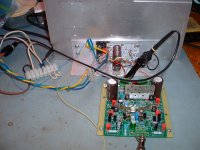
As shown, using some dual die Alfets, which were purchased for a OPC LME49830 build. Same as Exicon ECW20N(P)160. +/- 65V supply, 400mA of bias.
What impresses me is the bias stability using a lateral fet design. bjt's and I assume verticals wonder around a fair bit.
It clips really clean and runs a 10Khz square wave near perfect into a 8 ohm resistive load, measured ~360nS symmetrical rise/fall times before the isolation filters.
Gutter guard cut offs, make nice heatsinks") Does not have to be pretty to work well.
Does not have to be pretty to work well.
Even if you do not own a DH-xxx, this design with a simple output stage as shown makes a nice amp.
Enjoy
Rick
Jfet's arrived, passes the smoke tests, it makes wonderful sounding music. Still needs a lot of testing for me/us to say it is perfect enough and ready for release.
Needs to be run in a real DH-200/220, working on that with ticknpop, but look'n good so far.
As shown, using some dual die Alfets, which were purchased for a OPC LME49830 build. Same as Exicon ECW20N(P)160. +/- 65V supply, 400mA of bias.
What impresses me is the bias stability using a lateral fet design. bjt's and I assume verticals wonder around a fair bit.
It clips really clean and runs a 10Khz square wave near perfect into a 8 ohm resistive load, measured ~360nS symmetrical rise/fall times before the isolation filters.
Gutter guard cut offs, make nice heatsinks
Does not have to be pretty to work well.Even if you do not own a DH-xxx, this design with a simple output stage as shown makes a nice amp.
Enjoy
Rick
Attachments
Last edited:
Jfet's arrived, passes the smoke tests, it makes wonderful sounding music. Still needs a lot of testing for me/us to say it is perfect enough and ready for release.
Needs to be run in a real DH-200/220, working on that with ticknpop, but look'n good so far.
As shown, using some dual die Alfets, which were purchased for a OPC LME49830 build. Same as Exicon ECW20N(P)160. +/- 65V supply, 400mA of bias.
What impresses me is the bias stability using a lateral fet design. bjt's and I assume verticals wonder around a fair bit.
It clips really clean and runs a 10Khz square wave near perfect into a 8 ohm resistive load, measured ~360nS symmetrical rise/fall times before the isolation filters.
Gutter guard cut offs, make nice heatsinks
Even if you do not own a DH-xxx, this design with a simple output stage as shown makes a nice amp.
Enjoy
Rick
Nice work, Rick!
Cheers,
Bob
that is awesome...
Very nice preliminary work Rick, KUDOS! I am most excited to finally ~see~ beyond the circuit concept alone.
I have multiples of amp chassis to consider incorporating this into, then have opportunities for side by side comparisons [not mentioned as a challenge or to be critical of] Bob's much desired work and evolution of the driver board.
I cannot wait to hear them...
Jfet's arrived, passes the smoke tests, it makes wonderful sounding music. Still needs a lot of testing for me/us to say it is perfect enough and ready for release.
Needs to be run in a real DH-200/220, working on that with ticknpop, but look'n good so far.
As shown, using some dual die Alfets, which were purchased for a OPC LME49830 build. Same as Exicon ECW20N(P)160. +/- 65V supply, 400mA of bias.
What impresses me is the bias stability using a lateral fet design. bjt's and I assume verticals wonder around a fair bit.
It clips really clean and runs a 10Khz square wave near perfect into a 8 ohm resistive load, measured ~360nS symmetrical rise/fall times before the isolation filters.
Gutter guard cut offs, make nice heatsinks
Even if you do not own a DH-xxx, this design with a simple output stage as shown makes a nice amp.
Enjoy
Rick
Very nice preliminary work Rick, KUDOS! I am most excited to finally ~see~ beyond the circuit concept alone.
I have multiples of amp chassis to consider incorporating this into, then have opportunities for side by side comparisons [not mentioned as a challenge or to be critical of] Bob's much desired work and evolution of the driver board.
I cannot wait to hear them...
Last edited by a moderator:
planned modifications to a dh-200
Rick; I have read your comments regarding the Bob Cordell influenced/designed boards you are putting together for the Hafler DH-200. My audio system uses a DH-200 which has been in service since 1981. It seems to operate without fault, except that the connections at the rear (RCA's/binding posts) need replacement immediately. Because I have been upgrading my system a piece at a time (better pre-amp and new Rega turntable), it's time to do something about the power amplifier. I would like to be able to use the boards you're working on, but perhaps also replace the capacitors and transformer. What parts do you suggest or recommend? What would be the logical order of replacement starting with the connections at the rear of the amp? What is your estimate for when you think the boards might become available for release? Thank you!
Caveadapted
Hi Caveadapted,
I do not know exactly what is needed to upgrade a DH-200, since I have never done it. only as good as the weakest link comes to mind.
have you read through this thread to see what others have done?
need to research what others have done. changing the transformer is radical imo, unless it has issues, which I am un-aware of.
I could see changing the old big filter ecaps, best to test them first, but that would be finding a screw base type that is the same mechanically.
Sorry, it is a slow road to having the dh-220c ready for general availability. I would like to be sure that the dh-220c can "operate without fault" just like the original.
Last edited:
The original speaker and RCA connectors on the Haflers are terrible.
The power switch burns out from turn on inrush.
The filter caps are old now. A Thermistor and new caps ( 27,000uf fit ) but you must use the thermistor with the new bigger caps. When I get a chance I‘ll test the DH 200s with my Cheapmodo jig for snubbing the diode bridge and list the CRC snubber values for those without the jig. Transformer doesn‘t need to be changed
Thank you forreplies to dh-200 inquiry
rsavas; ticknpop; Thank you both for your prompt replies. The slow road to having the dh-200c ready for release is understandable. Thanks for your comments on the caps and transformer. Don't know why, but I have never had problems with the power switch. Thank you also for the comment regarding reading what other have done. Well advised, and I will do so. I am novice and learning, so appreciate your replies, including the comment on the thermistor and new caps. I'll patiently await further news on the dh-200c.
rsavas; ticknpop; Thank you both for your prompt replies. The slow road to having the dh-200c ready for release is understandable. Thanks for your comments on the caps and transformer. Don't know why, but I have never had problems with the power switch. Thank you also for the comment regarding reading what other have done. Well advised, and I will do so. I am novice and learning, so appreciate your replies, including the comment on the thermistor and new caps. I'll patiently await further news on the dh-200c.
No need for Krispy Kreme. The jfets will be a dual footprint using TO-71-6(socketed) and sot-23-6 on the back, in the 2nd rev, the first rev was only the TO-71, agree, there is not much $ to be saved with the sot-23, thus the choice.
+/-97V, man that is pushing it, using 100V spec'd cap parts, yes it is BBQ season for sure.
maybe time order up your jfets, I am still waiting for mine. I asked trendsetter if they could snail mail them to me, they obliged, since they wanted 2x more money to ship than what they were worth. They only had one lsj689 in stock, but I see that they have re-stocked. I have the contact info if you need it.
Here's some info that might be useful. I ordered a few from them TO-71 in the end of March for a low power amp design. I just tested them. My results:
LSK489: 3.41mA (A), 5.46mA (B), 6.04mA (B), 7.80mA (B)
LSJ689: 6.47mA (A), 7.10mA (B), 11.76mA (B-C), 14.56mA(C)
Not the results I was hoping for, but I have two usable sets from purchasing four sets. Too bad they are not available for purchase in different grades like the other Linear Systems fets. Good luck with the project.
info on test setup
https://www.diyaudio.com/forums/parts/338479-idss-tests-lsk489-lsj689.html#post5805450
Last edited:
Here's some info that might be useful. I ordered a few from them TO-71 in the end of March for a low power amp design. I just tested them. My results:
LSK489: 3.41mA (A), 5.46mA (B), 6.04mA (B), 7.80mA (B)
LSJ689: 6.47mA (A), 7.10mA (B), 11.76mA (B-C), 14.56mA(C)
Not the results I was hoping for, but I have two usable sets from purchasing four sets. Too bad they are not available for purchase in different grades like the other Linear Systems fets. Good luck with the project.
info on test setup
https://www.diyaudio.com/forums/parts/338479-idss-tests-lsk489-lsj689.html#post5805450
When implementing full complementary LTP differential input stages with N-type and P-type dual monolithic JFETs, matching of Idss between the P and N devices is not as important as one might think. In use, the operating Vgs of the P and N devices will go to whatever voltage it takes to cause the device pair to operate at its available tail current.
What is more important in such an input stage is that the transconductance of each LTP be about the same. For devices of a given process, the operating transconductance is mainly a function of operating current, rather than Idss. In other words, two JFETs from the same process may have different Idss and threshold voltage, but the same transconductance. This is because the transconductance parameter Beta in the SPICE model is similar for devices from the same process.
However, it turns out that the transconductance for a P-channel device and an N-channel device may have different Beta, and consequently different transconductance at a given current value. What this means is that even if you use P and N devices with exactly the same Idss, you will not likely have the same transconductance in the P and N pairs, even if the tail currents are the same.
Sometimes, source degeneration resistors will be added to one of the pairs to make the transconductance of the P and N pairs the same at the same operating current.
The observation that gm for devices from the same process depends mainly on operating current rather than Idss makes the paralleling of pairs to reduce noise more practical without resort to close matching, as long as each of the paralleled pairs has its own tail current source. This approach was used to advantage in the VinylTrak MC preamp where four LSK389 devices were connected in parallel to achieve low noise.
That all having been said, I do wish that the LSK489 and LSJ689 parts were made available in Idss-graded versions.
Cheers,
Bob
Dimensions for the power supply caps?
Hi,
Does anyone have the dimensions for the stock power supply filter caps (C403 & C404) used in the DH-220? Or if there is already a post in this thread please point me there (my search efforts aren't finding it).
I thought I took measurements the last time I had the cover off to replace the power switch, but that piece of paper didn't make it back into the file with my Hafler kit building instructions :-(.
I'd like to do a "drop in" replacement of the originals, so physically I need to match the diameter, be less-than-or-equal-to the height, and have the same screw terminals, correct? If anybody has the dimensions I can order parts before I pull the amp out of the equipment shelving and take the cover off again.
Thanks,
Alan
A few questions about use of LSJ689/LSK489
With the explanation provided this makes the floating style of the complementary sound like even more of a challenge and I have a few questions.
Does different output impedance of the LTPs due to degeneration resistors have an effect on the rest of the circuit?
If you do you use independent CCS for the LTPs (or were to try and match gm for a given trail current) is it best to measure amplitude at the LTP or at the VAS? Could using different grade Hfe transistors in the VAS be an alternative way of reaching a balanced push pull voltage before the output stage?
Thanks for your time
Thanks for the clarification Mr Cordell. The application notes you've written and your book are my most valuable resources. As an electrical engineering student I feel like the art of analog circuitry design and understanding is being lost to Arduinos and breakout boards. I'm struggling to find a professor to work with for an audio based junior/senior design project... if I said the word 'drones' it would not be so tough.What is more important in such an input stage is that the transconductance of each LTP be about the same. For devices of a given process, the operating transconductance is mainly a function of operating current, rather than Idss. In other words, two JFETs from the same process may have different Idss and threshold voltage, but the same transconductance. This is because the transconductance parameter Beta in the SPICE model is similar for devices from the same process.
However, it turns out that the transconductance for a P-channel device and an N-channel device may have different Beta, and consequently different transconductance at a given current value. What this means is that even if you use P and N devices with exactly the same Idss, you will not likely have the same transconductance in the P and N pairs, even if the tail currents are the same.
Sometimes, source degeneration resistors will be added to one of the pairs to make the transconductance of the P and N pairs the same at the same operating current.
The observation that gm for devices from the same process depends mainly on operating current rather than Idss makes the paralleling of pairs to reduce noise more practical without resort to close matching, as long as each of the paralleled pairs has its own tail current source. This approach was used to advantage in the VinylTrak MC preamp where four LSK389 devices were connected in parallel to achieve low noise.
That all having been said, I do wish that the LSK489 and LSJ689 parts were made available in Idss-graded versions.
Cheers,
Bob
With the explanation provided this makes the floating style of the complementary sound like even more of a challenge and I have a few questions.
Does different output impedance of the LTPs due to degeneration resistors have an effect on the rest of the circuit?
If you do you use independent CCS for the LTPs (or were to try and match gm for a given trail current) is it best to measure amplitude at the LTP or at the VAS? Could using different grade Hfe transistors in the VAS be an alternative way of reaching a balanced push pull voltage before the output stage?
Thanks for your time
Thanks for the clarification Mr Cordell. The application notes you've written and your book are my most valuable resources. As an electrical engineering student I feel like the art of analog circuitry design and understanding is being lost to Arduinos and breakout boards. I'm struggling to find a professor to work with for an audio based junior/senior design project... if I said the word 'drones' it would not be so tough.
With the explanation provided this makes the floating style of the complementary sound like even more of a challenge and I have a few questions.
Does different output impedance of the LTPs due to degeneration resistors have an effect on the rest of the circuit?
If you do you use independent CCS for the LTPs (or were to try and match gm for a given trail current) is it best to measure amplitude at the LTP or at the VAS? Could using different grade Hfe transistors in the VAS be an alternative way of reaching a balanced push pull voltage before the output stage?
Thanks for your time
Thanks for the kind words. I am also disappointed that the teaching of analog circuit design seems to be on the decline compared to that for other areas. But there is so much in electrical engineering these days that it is probably a challenge for educators to choose their priorities. Quite a few years back the late Marshall Leach taught an audio-centric undergraduate course at Georgia Tech that was wildly successful. It was based on his book. One of the key things to the popularity and effectiveness of the course was that audio was the hook that got students interested. The material also gave students good analog EE intuition and hands-on experience. Marshall was a great educator. I'd love to see my book get used in some early-level EE courses in 2-year or 4 year colleges. It is obviously not a high-level textbook, but if it got more students interested in analog design it would have served its purpose. I think it could also serve as the basis of some useful lab experiments. We'll see
.While the use of degeneration resistors will have some influence on the output of the LTPs, it may not make much difference in comparison to everything else. For example the output impedance of the un-degenerated pair of devices may be higher to start with as a result of their lower operating gm (which was the reason we added degeneration to the other side in the first place). The natural output impedance of P and N-channel devices operating at the same drain current may not be the same anyway. Finally, in typical Miller-compensated amplifier designs, differences in LTP output impedance will tend to matter largely only at lower frequencies below the open-loop bandwidth frequency, where there is less concern anyway. This is largely because the shunt feedback from the Miller compensation capacitor effectively makes the output node of the LTP a low-impedance node anyway.
Definitively don't try to improve matching of LTP gain by fooling around with beta of the VAS transistors. More beta in the VAS transistors, even if one is 150 and the other is 300, is usually better. And, as usual, I recommend using a 2T VAS.
Hope this helps.
Cheers,
Bob
Questions about Hafler DH500 power supply mods
Hi All,
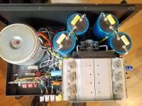
I just purchased an HF500 off Ebay. When I opened it up I saw that the power supply has been modified; instead of the single large transformer there are two large torroids stacked, (Talema 2185 (0500-1-130)). And instead of the stock capacitors there are 4 x "Capacitor Technology" 3800 uF caps.
Anyway I have a few initial questions:

Ron
Hi All,
I just purchased an HF500 off Ebay. When I opened it up I saw that the power supply has been modified; instead of the single large transformer there are two large torroids stacked, (Talema 2185 (0500-1-130)). And instead of the stock capacitors there are 4 x "Capacitor Technology" 3800 uF caps.
Anyway I have a few initial questions:
- Does anybody known if "Capacitor Technology" caps are considered good for this kind of application? What are considered desirable characteristics for a power supply cap, and can those characteristics be measured easily?
- Is "more better" with respect to capacitance in a power supply as long as in-rush current and such are properly handled?
- What is the consensus as to whether bypassing the large caps with the 1 uF caps (as shown below) is a good idea? I seem to have seen some discussion that said it was at best useless to do this, but I'm not sure if it's referring to this exact context.
Ron
Attachments
Ok, I think I found some some threads more appropriate for these questions.
n
- Does anybody known if "Capacitor Technology" caps are considered good for this kind of application? What are considered desirable characteristics for a power supply cap, and can those characteristics be measured easily?
- Is "more better" with respect to capacitance in a power supply as long as in-rush current and such are properly handled?
- What is the consensus as to whether bypassing the large caps with the 1 uF caps (as shown below) is a good idea? I seem to have seen some discussion that said it was at best useless to do this, but I'm not sure if it's referring to this exact context.
DH 500 Amp
Hi:
This looks like a DH 500 modified by Musical Concepts .
I have one like this and Musical Concepts rated this amp at about 350 Watts per channel.
Contact Musical Concepts / Musical Design Home for more info.
If not please let me know and I will dispose of this amp for your safety , just send it to me for disposal.
Hope this helps
Ed
njvet01@yahoo.com
- Home
- Amplifiers
- Solid State
- Hafler DH-200/220 Mods