gootee,
Don't Maggies get really ugly when over driven and have a habit of going "
poof"? Maybe two pair of Peerless XLS's as woofers. They are good clear up to 200 Hz or so which would be a big help to the MG-12's. ( old paper ones, no idea about the new metal cones. I don't like metal cones). I am sure the guys in the sub threads could come up with ideas to tax the Adcom while getting every cop in town knocking on the door which you won't be able to hear anyway.
I don't know. I guess it's all relative. Maggies might still sound much better than cones when overdriven (but I don't know that they do). But they might also seem to sound extra-bad when overdriven just because they sound so perfect otherwise. Also, it's pretty difficult to overdrive them. The main thing I notice, at uncomfortably-loud SPLs, on a two-way Maggie like my MG-12s, is that the bass is shaking the whole panel enough that it starts to audibly modulate the mid-range and treble. It doesn't sound good but they're too loud to be in the room with, then, anyway.
I have never heard that they can easily go "poof". What's to go poof? It's just a long piece of wire or foil, glued to some Mylar. I don't have the true-ribbon tweeters that most of the 3.x (and most of the 2.x) models had. Perhaps those are more fragile, especially when people remove the fuses.
If the wire or foil did break, I could glue on a new one (although that might take all day, to do correctly). But I suppose if it got hot-enough to melt through the mylar, the repair would be more involved (I might need some tape in addition to the glue <grin>). I've never heard of that happening, though. Actually, I imagine that the mylar membrane would have to be replaced, if all of the wire got that hot at the same time. But I have had one of my Maggies playing in the nude for me, for over half a year, and have often touched her wires after she's done, and they have never even been warm, that I could tell.
In case you aren't familiar with magnetic planar speakers, they are extremely simple. There are columns of magnets a few millimeters behind a large, tensioned mylar membrane. But the poles of the magnets are the large faces (rather than the ends), which are oriented toward the mylar. Alternating columns have all North and all South facing the membrane. A wire glued to the mylar between two of those columns will be in a magnetic field that is mostly parallel to the mylar, so a current in the wire will have a force induced on it that is perpendicular to the mylar, and either inward or outward depending on the direction of the current. If you use the correct cross-sectional area and length for the wire or foil, each driver's wire or foil will have a 4-Ohm resistance. And they stay almost purely resistive until well over 10 kHz. Hook the ends of the wire or foil to an amplifier output (or crossover) and they're good to go! Mine each have a fuse only for the tweeter section, which is foil.
My 4-Ohm midbass sections are each about 369 square inches. A cone woofer would have to be almost 22 inches in diameter to be as large. But I don't get any of the bass "boominess" artifacts, like box speakers have. And the imaging and clarity are just "to die for". (The bigger maggies have 500-800 sq in woofers, and are three-ways too.)
Many people think that they need sub-woofers, especially with the smaller maggies like mine. But I have never had that urge. Maybe it's my room or room treatments but I think that they sometimes have too much bass. And I can't believe that subs could be added without somehow betraying the soundstage image and the accuracy and clarity.
I have 2Ces set up right next to them and ready to play with the press of one button. But I almost never press that button, if that tells you anything.
Last edited:
"A cone woofer would have to be almost 22 inches in diameter to be as large"
If it was a dipole, correct.
Two 15s in a dipole configuration would also have the same kind of area.
A 12 or two 8s in a vented box would be able to play louder.
IMO, maggies do bass, but mid-bass can sound kind of thin. Compared to Stax phones they can make male vocalists sound like they only have one testicle.
What do you mean with really hard?In my study, it turns out good protection circuits are really hard.
The main goal should be to protect the speakers from a too high dc offset (this can really burn coils!), so it should be quite straightforward to sense the dc offset and de-energize a relay coil. This relay can be used also for a delayed "turn on".
Sure, that's the main reason to have a preampBig second on the preamp as you must have a low Z source for lowest noise through the IPS.
")
This can be done in the preamplifier if it has a switched mains socket.By remote, I meant remote power on and off.
But i don't see a reason to have a remote power amplifier turn on. Do the other electronics in the system have it? If needed I would prefer to do a "mains conditioner" with delayed plugs to switch on in the correct sequence all the electronics and, if needed, a remote turn on for all the system with a single remote control.
Ciao
Paolo
My ears, YMMV, is Maggies have ugly breakup. I know older ones usually with the ribbon tweeter. Maybe it is from people removing or changing fuses, but I have seen several panels fried open. Don't get me wrong, I like them very much when set up correctly.
The purpose of a sub is not more bass, but cleaner bass. Itf you take the load of the mid-woofer at 70 or 80 Hz, they are much cleaner. That low it is actually easier to move the subs around to work with the room treatments for smoother bass.
Don't know about anyone else's power switch in their preamp, but non of mine can switch a power amp. Tuner is about it. One still wants to have a delay to prevent a power glitch from turning it off and on quickly. 15 to 30 seconds. On my main system, I have a Furman sequencer with my own set of filter banks. It is controlled by the 12V remote line from the preamp. In my office, I don't need the sequencer, just a remote signal like most modern units. Of course it could be built externally.
By really hard, protection is a set of non-perfect tradeoffs. Read Self, Didden, Cordell etc.
Fuses are way to slow to protect much other than maybe the transformer. Relays may be fast enough to keep your woofer from leaving the cabinet, but not always. Probably enough to prevent a fire. They are not fast enough to prevent failure of silicon fuses. ( remaining outputs). A crowbar has to be able to deal with the cap bank, so it has to be massive to be fast enough. Everything degrades the sound. Sense circuits add capacitance and noise, relays less than perfect contacts and on and on. Fast sense without false trigger, another hard problem.
Sorry, I'm always considering my personal system, not commercial ones. In my case it is not a problem to implement a switched plug for the ampDon't know about anyone else's power switch in their preamp, but non of mine can switch a power amp. Tuner is about it. One still wants to have a delay to prevent a power glitch from turning it off and on quickly. 15 to 30 seconds.
Is it so different if the unit is switched off cutting the mains instead of the remote signal?On my main system, I have a Furman sequencer with my own set of filter banks. It is controlled by the 12V remote line from the preamp. In my office, I don't need the sequencer, just a remote signal like most modern units. Of course it could be built externally.
an we all agree about thatBy really hard, protection is a set of non-perfect tradeoffs. Read Self, Didden, Cordell etc.
Fuses are way to slow to protect much other than maybe the transformer.
A relay normally activates in milliseconds. Your integration over the measured output voltage has to be longer, several orders of magnitude.Relays may be fast enough to keep your woofer from leaving the cabinet, but not always. Probably enough to prevent a fire.
I'm not going to use a crowbar in the amplfier (is there any commercially available amp with this option?), the cost of a really effective circuit is more that the damage I can get from a failure.They are not fast enough to prevent failure of silicon fuses. ( remaining outputs). A crowbar has to be able to deal with the cap bank, so it has to be massive to be fast enough.
If the goal is the best reproduction, since I'm not designing an amplifier that has to go on the mass market, I get rid of all the protection circuits. I accept the risk. It's a matter of cost vs benefits. It is useless to spend 2k$ on (for example) a better CD player and live with the protection circuit that is degrading the sound: I save the 2k$ to repair the system in case of failure. I mean, this is an extreme consideration. Should I design a personnel safety system for a nuclear plant the attention I would pay on protection circuits is going to be different from the design of a power amplifier....Everything degrades the sound.
circuits add capacitance and noise, relays less than perfect contacts and on and on.
Capacitance: if the power amplifier suffers from the added capacitance of this circuit, well, I cannot use it with my electrostatics! And it won't be stable with other "fancy" crossovers you can find on some speakers...
Noise: my "feeling" is that the noise you pick up with the speakers cables is higher than the one introduced by this protection circuit.
Relays perfect contacts: there is no perfect contact! Should I solder then the speakers cable directly on the output devices?
(also the solder joint is a contact, but anyhow...)
Fast sense without false trigger, another hard problem.
Should the protection be based on the output voltage, current, energy or power? This makes a lot of difference...
Ciao
Paolo
Hello all,
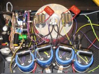
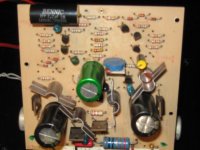
This DH200 is on my bench currently. It was given to friend of mine, and he passed it to me for some simple work. He had no idea it was modified, so I was pretty surprised when I opened it up and saw that it had been completely rebuilt (see attachments).
The filter caps are 75Vdc Nippon Chemicons, and they dropped the rails to +/-56Vdc with the new toroids. The bridge rectifiers are IXYS FRED 68A/600V. They added bypass caps on the mosfets, and upped the value of the on-board bypass caps, as well as the feedback cap using Muse parts. They removed and jumpered the VAS pre- devices, Q7/Q10, and re-did the output wiring.
This, IMO, is all going to far with one of these amps, and the extra noise and hum on the output says this amp was not treated with care. I intend to return the circuitry back closer to stock, as well as fix the DC offset problem with the left channel.
Attachments
What, no one has removed the input cap and added a dc servo to this circuit?
IMO, a servo is not really necessary for these amps. The PC19 boards have a DC Offset adjustment which does the trick fine. Even the PC6 boards in the 200 aren't really difficult, it just takes some matching of the input stage transistors, which should be done anyway.
Getting rid of the input cap isn't really a worthwhile goal, but it can be done without a servo. Just look at the Leach Low TIM.
depending on how far one is willing to go with modifications to either the dh-200 or dh-220, another logical progression is to recreate a version of the hafler xl-280 front end (note the official version uses unobtanium jfets) or borbely's servo 50 or all-fet front ends.
mlloyd1
mlloyd1
I have been contemplating mods to my 220 from what I learned about my 120. What I have learned so far:
The HEXFRED bridge and modern caps were well worth it. Hexfred does not mean no snubbers, but reduced. Scope it out under heavy load. The 120 had a lot of extra wiring for mono and Danyaquad and input pots that were all unnecessary. Better jacks and binding posts while not audible, are reliable.
The gate stoppers are the same value for P and N. This is wrong. They should be selected based on the output capacitance. 680 and 470 or higher seem to be popular. It will do wonders for parastatics. Put the predrivers back in and at least put 2N5551's in instead of the 5550's. Half the noise. I would replace all the resistors in critical locations with 1%. Why go through the trouble to match the inputs if the degeneration resistors are not close? With bypassing on the heat sinks and careful ground routing, you can probably ditch half the compensation caps. My 120, I switched to standard miller compensation and a single feedback 3.3p. Going to much bigger input caps moves the distortion problems out of audio range. 47u? You can do the same on the feedback. The 220 ties the low power and high power grounds together through a cap. I would split them and return to the star ground independently. Then replace the output fuse with a protection circuit and relay. 3 different grounds. Yea, I got a problem with that. Do I see blue LED bias parts in there? Noise and hum are not about care, but about poor execution.
Put the predrivers back in and at least put 2N5551's in instead of the 5550's. Half the noise. 3 different grounds. Yea, I got a problem with that. Do I see blue LED bias parts in there? Noise and hum are not about care, but about poor execution.
Assuming this was directed at me... This amp had MPS8099/8599 for the diff pairs, and BC556/546 for the current sources. On the bad channel I plan on replacing all with 2N5551/5401, with new degeneration resistors.
The blue things are old school ceramic caps.
Hello all,
... They removed and jumpered the VAS pre- devices, Q7/Q10, and re-did the output wiring.
This, IMO, is all going to far with one of these amps, and the extra noise and hum on the output says this amp was not treated with care. I intend to return the circuitry back closer to stock, as well as fix the DC offset problem with the left channel.
My 2 cents.
Removing the VAS pre-devices is a bad idea unless you radically change the input stage current or devices...
The ground return to the toroid securing screw may create a shorted turn and result in humm....
Probably a good idea to go back closer to stock...
Good luck
Fab
.....
The ground return to the toroid securing screw may create a shorted turn and result in humm....
.......
more than agree with that
I wasn't sure about that, glad you chimed in fab/zen mod
My previous Hafler experience is mostly with P125's and P230's with three wire power cords. In the original DH200 design the chassis is connected to the "signal" gnd through the RCA jacks. This unit has insulated jacks installed. Should the chassis be left floating, or connected to central gnd as it is now (only not through the transformer mounting bolt)?
My previous Hafler experience is mostly with P125's and P230's with three wire power cords. In the original DH200 design the chassis is connected to the "signal" gnd through the RCA jacks. This unit has insulated jacks installed. Should the chassis be left floating, or connected to central gnd as it is now (only not through the transformer mounting bolt)?
Assuming this was directed at me... This amp had MPS8099/8599 for the diff pairs, and BC556/546 for the current sources. On the bad channel I plan on replacing all with 2N5551/5401, with new degeneration resistors.
The blue things are old school ceramic caps.
Have you looked at 2SA970 and 2SC1085 where the SOA allows it?
Have you looked at 2SA970 and 2SC1085 where the SOA allows it?
Pin out of 2SA970 is different (bce instead of cbe).
Fab
Pin out of 2SA970 is different (bce instead of cbe).
Fab
So. Legs bend.
I conversed with John Hillig at Musical Concepts about this DH200. I was told the mods may have been done there, or inspired by his work.
He was very responsive and acknowledged that some of the mods may have been based on his work, but it was definitely not done by them. He agreed with Fab and zen mod about the central ground's location causing a shorted turn with the toroids, so I'll be moving that as I said earlier.
He was very responsive and acknowledged that some of the mods may have been based on his work, but it was definitely not done by them. He agreed with Fab and zen mod about the central ground's location causing a shorted turn with the toroids, so I'll be moving that as I said earlier.
The DH200 is back together and running perfectly. I replaced the input diff pairs in both channels and the current source devices with new ONsemi 2N5551/5401. Each group had the same date codes, and they were very closely matched out of the bag on my Heathkit IT-18. I ended up with 5-10mVdc offset on each channel. I also replaced the 22R emitter degeneration resistors for the diff. pairs with 1% metal film, which may have helped.
I also re-installed the VAS pre-drivers, Q7/Q10, moved the central ground location, and installed a three prong AC line cord. The amp is now very low noise, and sounds great.
I also re-installed the VAS pre-drivers, Q7/Q10, moved the central ground location, and installed a three prong AC line cord. The amp is now very low noise, and sounds great.
- Home
- Amplifiers
- Solid State
- Hafler DH-200/220 Mods