I forget, is the PC-19 board for the DH-200 or Dh-220?
The output MOSFETs are very rugged and if sanely used in a properly fused amp they very rarely fail. You could always swap them in pairs from one channel to the other to check which ones do and do not work.
Caution, each MOSFET should have a number stenciled on it. These devices must be used in matched pairs (matched P channel devices and matched N channel devices). A matched pair will cost $30+ and if 4 pairs are used in an amp that totals $120. You could purchase another DH-200 for about this cost, use it for spare parts, and sell off the remainder.
The original DH-200 (PC-6 boards?) sounded better with some mods. The DH-220 incorporated most of these mods into its circuit. There is little you can do to mod the DH-220.
Hope this helps.
Dick
Excuse me if I travel a path blazed long before, as I'm a newbie and haven't searched all posts historically.
A year ago, I began the "HiPer Hafler" project on my then 22-year-old DH-220. The salient aspects of my mods are:
a) Musical Concepts PA-3B driver boards
b) Plitron/Musical Concepts toroidal power transformer
c) Dual-mono power supplies
d) 48,000uF per channel PS capacitance
e) IXYS FRED diode FWBs in each channel
f) A step-start (!) circuit on the AC input
g) Total rework of ground/common wiring
The step-start is probably the one feature that's not likely to be found elsewhere. It comes from my many years working with high-power radio and TV transmitters, where such circuits are commonplace. The essence is simple: there's a resistor in series with the AC connection to the toroidal power transformer input and a relay shorting that resistor. The relay closes when PS voltage approaches normal, thereby limiting inrush current in the PS. The lights don't dim, the power switch doesn't fail, and the "step" (i.e., relay closure) occurs in less than a second from initial application of power. And there's much less "thump".
This was a fun project. Did the amp sound better? Yes. Does it equaly my Odyssey Stratos Extreme? No. Would I do it again? Yes!
The overall clarity of the amplifier improved, along with its ability to handle LF transients. It doesn't equal the Odyssey on the bottom end, but the latter amp has twice the PS capacitance, so that result's not surprising. My general impression is that it has a slight edge over the stereo Odyssey on midrange and highs. But that advantage diminishes with the Odyssey in its Mono Extreme configuration.
I'm looking forward to another 20 years of good service from this amp, albeit in my second system.
What would be interesting, sonically, is to operate 2 DH-220s, each as a mono, with one channel with input shorted, sinking the return lead from the speaker driven by the other channel; i.e., in an unbalanced bridge mode. Has anyone tried this?
Proposed DH-200 Mods
The PC-19 boards are those found in a DH-220. I noted that they still have mylar caps and carbon resistors on the PC-19 board. Marsh and Jung replaced their resistors with MOF. I have heard the noise reduction of Metal Film over carbon resitors in other projects. They also suggested the use of polystyrene caps. Sound wise, in the signal path polysyrene should sound better than mylar caps.
I have not set down and compared the circuits to determine what mods if any were included in the PC-19 board over the PC-6. With the exception of the components listed above are there any reasons not to "upgrade" these caps and resistors on the PC-19 board?
I have heard improvements in the sound that comes from my modified PC-6 Board DH-200. The Marsh and Jung Pooge article from The Audio Amateur magazine made extensive mods to the DH-200 and they documented the results they heard. I have heard with my own ears that the unit can sound better after some mods. The Pooge and Muscial Concepts mods as well as this thread lead me to believe that the DH-200 can be satisfactorilly modified.
Is there something that I am overlooking regarding modifying the DH-200?
Dick West said:I forget, is the PC-19 board for the DH-200 or Dh-220?
The PC-19 boards are those found in a DH-220. I noted that they still have mylar caps and carbon resistors on the PC-19 board. Marsh and Jung replaced their resistors with MOF. I have heard the noise reduction of Metal Film over carbon resitors in other projects. They also suggested the use of polystyrene caps. Sound wise, in the signal path polysyrene should sound better than mylar caps.
The original DH-200 (PC-6 boards?) sounded better with some mods. The DH-220 incorporated most of these mods into its circuit. There is little you can do to mod the DH-220.
I have not set down and compared the circuits to determine what mods if any were included in the PC-19 board over the PC-6. With the exception of the components listed above are there any reasons not to "upgrade" these caps and resistors on the PC-19 board?
I have heard improvements in the sound that comes from my modified PC-6 Board DH-200. The Marsh and Jung Pooge article from The Audio Amateur magazine made extensive mods to the DH-200 and they documented the results they heard. I have heard with my own ears that the unit can sound better after some mods. The Pooge and Muscial Concepts mods as well as this thread lead me to believe that the DH-200 can be satisfactorilly modified.
Is there something that I am overlooking regarding modifying the DH-200?
Hi Karl,
"there's a resistor in series with the AC connection to the toroidal power transformer input and a relay shorting that resistor. The relay closes when PS voltage approaches normal, thereby limiting inrush current in the PS. The lights don't dim, the power switch doesn't fail, and the "step" (i.e., relay closure) occurs in less than a second from initial application of power. And there's much less "thump".
Can you give more detail as to the resister value and relay specification, and how big is this add-on module? Do you have a schemetic for it? Thanks in advance.
Regards,
Tom
series output choke and Graham Maynard
Regarding mods, has someone tried to remove the series output choke in the DH-200/220 amps?
Here I make reference to the Graham Maynard's article on Class-A imagineering in Electronicx world magazine". Graham seems to claim that the output inductor increase the loudspeaker induced amplifier distortion.
Thomas001 said:Hi Karl,
"there's a resistor in series with the AC connection to the toroidal power transformer input and a relay shorting that resistor. The relay closes when PS voltage approaches normal, thereby limiting inrush current in the PS. The lights don't dim, the power switch doesn't fail, and the "step" (i.e., relay closure) occurs in less than a second from initial application of power. And there's much less "thump".
Can you give more detail as to the resister value and relay specification, and how big is this add-on module? Do you have a schemetic for it? Thanks in advance.
Regards,
Tom
Hi Tom,
Must be something like this:
Attachments
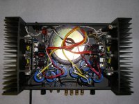
This responds to Tom's query regarding my step-start circuit.
I used a 110VDC relay, Potter & Brumfield K10P-11D15-110, connected across one of the two "quasi-mono" power supplies via a 2K ½W series resistor, with its contacts (2 sets in parallel) shorting out a 5 Ohm, 50W resistor which is in series with the 120VAC feed to the toroidal power transformer primary.
When the amp is first turned on, the 5 Ohm resistor limits the instantaneous inrush current (and, in essence, the charging current through the PS caps) to 24A (12A per supply). This keeps the FRED bridges well within their ratings and reduces overall stresses.
Once the power supply charges up to around 110V or so, the relay closes and places the amp in the "run" mode. If I wanted to use speaker-delay relays, I would slave these to the closing of this "second step" relay, if not using a separate 5-sec time delay circuit.
The sketch provided by Elso is not what I did, but it should also work. It's based on the dynamic impedance of the power supply loading down an AC relay and preventing its coil from having sufficient voltage until the supply is sufficiently charged.
The 50W rating on the resistor is somewhat arbitrary. One can probably get by with less, but I've not performed the integration calculation necessary to more precisely define what's needed.
In the attached picture, the resistor and relay are seen in the upper right-hand corner.
Karl
Attachments
Hi Karl,
Sorry to border you again, but I really your help in building the relay using the recommended K10P-11D15-110. As per the K10 series wiring diagram (http://www.carlton-bates.com/Current_Catalog/169.pdf), can you please tell me how to connect the incoming AC, the 2k paraell and the 5 R resistor and the AC output. You help in this matter is much appreciated.
Regards,
Tom
Attached is the schematic for the Hafler step-start.
Basically, the 120VAC interlock circuit through the thermostats is opened, with the wire removed from the thermostat attaching to one of the relay contacts, the other contact is jumpered to the thermostat lug where the wire was removed, and the 5 Ohm resistor is connected across the relay contacts. So there's 5 Ohms in series with that interlock loop, shorted out when the step relay closes.
Sorry that there's not a comprehensive schematic & instructions. I did take a number of photos during the modification effort, showing how all this gets assembled. But, being a road warrior, I've not had time to write/package all of it up.
Hope this helps,
Karl
Attachments

Hafler delay circuit
KarlDL,
Thanks for posting the schematic. Now, it raises more questions.
Is the relay's coil you are using run by 110VAC or DC? Your schematic shows the relay coil with + and - symbols.
Your diagram about how to wire up the series power resistor is clear but what is the relay coil attached to, 110VAC or the power supply's DC?
Thanks
"Basically, the 120VAC interlock circuit through the thermostats is opened, with the wire removed from the thermostat attaching to one of the relay contacts, the other contact is jumpered to the thermostat lug where the wire was removed, and the 5 Ohm resistor is connected across the relay contacts. So there's 5 Ohms in series with that interlock loop, shorted out when the step relay closes."
Hafler Delay Circuit
KarlDL,
Aha. Now that I read the fine print I see you are using a 110 VDC relay.
Now, if it is connected across the two secondaries is their combined voltage too high for the relay's coil. We know the amp has rails of +/- 65VDC, depending on initial VAC level. If we add 65+65 we get 130. Is this a safe voltage for the relay's coil?
Do the 2K resistor in series with the relay coil and the coil's resistance make a voltage divider which reduces the 130VDC to a lower level?
Thanks for helping to educate us.
Dick asked whether the 110V relay used in my step-start circuit is AC or DC, and how that coexists with the 130V total PS voltage (rail-to-rail).
The rated current for this DC coil is approximately 10mA. The 2K series resistor drops approx 20V at that current, hence the coil voltage is approx 110VDC under normal operating conditions.
There's an argument for using a larger-valued voltage-limiting resistor, based on the rated pull-in voltage of the relay. But I'm happy with the results obtained at 2K. Also note that the drop-out voltage rating for the relay is much lower than its pull-in rating, so the PS caps have to discharge significantly before the step-start relay releases.
Choky asked if anyone has reverse-engineered the Musical Concepts PA-3B driver board. I have done so, but I believe that there are errors in my original schematic trace; the apparent circuit topology doesn't seem fully logical. I will take another look at the board after the holidays end. It is a much simpler circuit than the original Hafler design.
Karl
KarlDL said:
Choky asked if anyone has reverse-engineered the Musical Concepts PA-3B driver board. I have done so, but I believe that there are errors in my original schematic trace; the apparent circuit topology doesn't seem fully logical. I will take another look at the board after the holidays end. It is a much simpler circuit than the original Hafler design.
Karl
"mebbe this is just old barking ,but I must ask again-it is possible to someone send me just PA3B schematic ?
I'm interested just for evaluating and I really have no need to build it ,in case that someone sez smthng about intelectuall property etc........."
If you just want to rip them off, order a pair of boards. By the time you reverse engineer them and sell 10 sets you will have made a pile of money.
Your baloney about 'evaluating' doesn't wash. They describe the topology in great detail, and even show the board layout with the traces.
Figure 2N540X/2N555X for the small plastic types and MJE340/350 for the larger pair.
Calculating the resistors is left as a design exercise.
If you're actually going to build one, the Miller cap (C11) and VAS feedback cap (C4) are best adjusted with a 'scope.
Schematic PA3B
May I have the schematic too?
djk said:"mebbe this is just old barking ,but I must ask again-it is possible to someone send me just PA3B schematic ?
May I have the schematic too?
- Home
- Amplifiers
- Solid State
- Hafler DH-200/220 Mods