infinia said:Mike,
From your description it seems the problem to be in the Mods that were added. Best to go slowly on them,
Thanks for good advice. I had run up the amp after I replaced the electrolytic caps and added polypropylene bypasses. At that stage there was no problem. I fact I still had the same DC offsets as when I started. I then changed the input to 47k and as warned by Fab my offset about doubled but the amp exhibited no other problems.
I then replaced feedback R22 to 47.5k to match the input R2 to get the offset back in line. The amp was again powered up and that is when I found almost full negative rail at the right channel. Upon teardown I found the bad solder joints on Q12. I thought at the time that Q12 was the culprit but it tested fine and went back in.
Today I brought up the AC voltage slowly to full 120 with nothing getting hot and with 61 volts on the supply rails I have almost minus 59 volts at the Rch output. Rather healthy offset
My quick guess is to focus on the low esr caps used as a bypass in the negative feedback connection up front in the diff amp. Low esr sometimes also results in higher leakage current. High leakage current at the input can cause DC offsets to rail in operation.
I had swapped caps from right to left on the board so if one had gone bad and was the problem the offset would have changed to full positive rail.
The electrolytics replaced C7 and C10 are as I see it supply filters for the input and the old ones tested bad thought the offset difference between channels remained after replacement.
You have gotten me to back tracking everything so we shall see I hope. Thanks again.
Resistor R38 on PC-19c
Greetings all,
I have a question regarding the DH-220. There is a resistor R38 on the PC-19c which is not on my DH-220 with PC-19b. Can anyone familiar with this amp please explain what this resistor does? This resistor is 22.1k connecting the positive side of the bias network and the base of Q12 to ground. I have added this slight mod to my amp as part of the Musical Concepts GXB mods many years ago but I have no idea what it does as I only have very basic curcuit understanding.
Thanks in advance
Dan.
mike in florida said:
... I then changed the input to 47k and as warned by Fab my offset about doubled but the amp exhibited no other problems.
I then replaced feedback R22 to 47.5k to match the input R2 to get the offset back in line. The amp was again powered up and that is when I found almost full negative rail at the right channel. Upon teardown I found the bad solder joints on Q12. I thought at the time that Q12 was the culprit but it tested fine and went back in. .....
..
mike,
R22 should be matched to R3 on the DH-200. R2 should be equal or lower (if high pre-amp output impedance) than R23 (for optimization of CMMR). On the DH-220, there is no matching but a DC offset adjust circuit.
The AC gain of the DH-220 amp is set by the ratio of R23 (2k2) on R25 (100).
Also, Dale/Vishay resistora do not have color band code but a numeric value including the factor of 10 (ex. 2002 means 20K) and it is easy to install the wrong value by mistake...
Make sure that Q12 is re-installed properly (B-C-E) too
Re: Resistor R38 on PC-19c
Dan,
It is often used to reduce the VAS gain in open loop of the amp thus decreasing the overall negative feedback factor of the amp. But usually there is another resistor from base of Q13 to ground too. Not everybody agree on the presence or not of these resistors...
Sze said:Greetings all,
I have a question regarding the DH-220. There is a resistor R38 on the PC-19c which is not on my DH-220 with PC-19b. Can anyone familiar with this amp please explain what this resistor does? This resistor is 22.1k connecting the positive side of the bias network and the base of Q12 to ground. I have added this slight mod to my amp as part of the Musical Concepts GXB mods many years ago but I have no idea what it does as I only have very basic curcuit understanding.
Thanks in advance
Dan.
Dan,
It is often used to reduce the VAS gain in open loop of the amp thus decreasing the overall negative feedback factor of the amp. But usually there is another resistor from base of Q13 to ground too. Not everybody agree on the presence or not of these resistors...
fab said:
mike,
R22 should be matched to R3 on the DH-200. R2 should be equal or lower (if high pre-amp output impedance) than R23 (for optimization of CMMR).
<snip>
Make sure that Q12 is re-installed properly (B-C-E) too
Thanks once more Fab, My Identifying R2 as R3 was a typo. I had correctly understood your advice. I never seem to properly proof read my stuff though. I also replaced R2 to it's original value of 2K2 . The negative rail offset was solved by replacing Q8, Q12 & Q11, Q13. They all tested OK but I was checking voltages at +5v, -5v and found no negative voltage on the bases when I passed about 12 volt rails everything past Q8 went down the chute. I realize nothing was going to stabilize at so low a voltage but I was just checking working back from the MOSFETS. I just went down and picked some gold priced NTE parts and all is normal. And yes I double checked B_C_E as well as NPN-PNP in the right places.
I'm getting a bit old so I try and over check my work (memory loss/CRS). I just got this thing back together and I'll let it settle in a bit but I think the fun is just beginning. I suspect the stability of the amp after the mods. Offset wanders a bit too much and and the current drifts too quick in small amounts. I took a little over an hour to bring it up to 125VAC and let it sit there another hour this afternoon so the caps should be settled in.
Tonight it is being fed 2mv white noise and all is running cool. I'll hook it up to the scope in the morning and play awhile. I think the whole network around C5-R23 may need work. It may be that I'm asking too much to get this circuit to work at 47K input. I have in the past designed tube amps that looked good on paper and measured good at Audio freq. but were indeed very good VHF oscillators .
I should have my orders from Mouser and Digi-Key Tues. so later next week I'll get to matching the input to get the offset down.
I will post progress and if stable I'll give some listening impressions with the present mods. (That's the amp being stable. I'm not sure about me.)
")
POOGED Hafler transistor blowup
I have a POOGE modified (a la Walt Jung) Hafler DH-200 that was working fine, but having reviewed the old article from Audio Amateur, I was going over it, refreshing my mind about the layout and checking connections. Based on a comment in the article, and thinking it might be a good idea, I loosened all the screws on the output transistors, dabbed a little contact cleaner on the screw thread only, and tightened them down again.
When I fired it up, only to check it (without any input or speaker loads), I heard an unusual amount of hum, then noticed that very quickly the heat sink on one side started getting very hot. I shut it off immediately, and hooked up inputs and speakers to verify. I ran it for another 15 seconds, with music, and clearly the left channel was now out (right played okay). The left had an intermittent light popping sound. Around this point the protection circuit popped in.
I shut it off and found the heat to be coming apparently from just one upper transistor on one side. Everything else seemed to stay cool (except the heatsink taking up the heat). Maybe the screw tightening thing was a foolish thing to do with 25 year old transistors? Has anyone heard of this before? (Actually, this side always ran a little hotter than the other one.)
I have built kits and changed out caps, but otherwise I am not a very experienced DIY'er. Never did transitors. I have a meter which is supposed to test transistors. I've never used it, but I thought of pulling the two MOSFETS on that side of the heat sink and checking them with the meter. The operation might kill them both, but I presume I would have to replace them as a matched pair.
--1) Okay, so first of all, does this seem like a likely scenario--that I set up a vulnerable 25 year old transistor for failure?
--2) How can I verify that this is the problem?
--3) If it is, advice about a good place in the US to get these MOSFETS for the DH-200. The numbers on these are: 571134, and under that 8044 (I noticed the numbers on all the output transistors are not exactly the same, but each pair are--maybe having to do with matched pairs? Anyway, these are the ones of concern.)
Thanks if you can help.
I have a POOGE modified (a la Walt Jung) Hafler DH-200 that was working fine, but having reviewed the old article from Audio Amateur, I was going over it, refreshing my mind about the layout and checking connections.
Based on a comment in the article, and thinking it might be a good idea, I loosened all the screws on the output transistors, dabbed a little contact cleaner on the screw thread only, and tightened them down again.
Some transistors are designed such that the case is electrically hot and most be insulated electrically, but not thermally, from the heat sink. I'll be you've introduced a short on the transistor. Try measuring case to heatsink impedance on the suspect vs. normal transistors and see if there's a difference.
Regards,
Rob
Thanks. And my apologies. I originally posted my above post in its own thread. I got impatient a little too soon, as there was no response at first, so I also posted it here. Later I heard from several people on my original thread.
Tomorrow I will try checking some of the things that people mentioned. I'll post results on my original thread.
However, while I'm here, I am curious what those of you who have fooled with the old DH-200's and DH-220's think about these old amps compared to newer ones. How do you think the originals stack up against Walt Jung style POOGED ones that are still around, or recently done, versus the Musical Concepts upgrade boards, versus other amps in the 100W/100W range? What would you do now to get the most bang (quality, actually) for your buck?
Thanks again for responding.
I built a voltage regulator for the voltage amplifier stages (PC-19) for the Hafler 220. I looked at FAB's designs (especially the 2005 version) and his comments which were, as usual, clear and convincing. I followed Darcy Stagg's design in Audio Amateur (1993, volume 4). FAB's VR would be cheaper to make than Staggs', but I liked the idea of separate transformers and higher capacitance in Stagg's design. I modified Staggs' PCB layout so that it would fit in the Hafler case (Staggs' was in an external case). My amp has a toroidal transformer and the VR sits on top of it with a shield in between. The rail voltages (w/o the VR) are about 67, and I set up the VR to 72 volts. I have not wired in the VR yet.
The main power rails go directly to the MOSFETS and the VR output goes to the PC19 rails (holes 3 and 10). This makes sense, but I'm confused about Staggs' recommendation to jumper (or replace with wire) D15, R31, D16 and R32. Maybe their removal goes without saying, but I did not notice this on FAB's design. Staggs' says that these devices decouple the main power rails from the low-level transistors and offset adjustment. Is there an advantage to replacing these diodes and resistors with wire? Are the diodes and resistors simply unnecessary, or would they cause problems if left in after rewiring the rails to accept the VR?
Any suggestions would be appreciated, and I'll give my impressions on the amp's sound after I put in the VR if anyone is interested. I could supply my PCB pattern too and tips on construction.
Diodes and resistors supply filters
Hi,
D15, R31, D16 and R32 (along with the caps) were mainly used in the original DH-220 or 200 to isolate a bit the driver stage from the big output power stage voltage variation and also during power OFF of the amp to allow the driver stage to have power for a longer time than the output stage to have a "cleaner" power OFF with less risk of audio thump.
With a regulated supply the driver stage is far away better isolated from the Output stage power voltage variation upon high current demand (loud music) than with the diode/resistor/cap filter.
Usually with a series regulator where its output impedance is low it is "better" to remove the resistors to fully get the best from the regulator. However, depending on the regulator it may be prone to very small oscillation that appear like an increase of ripple voltage (on the regulated voltage which is still a lot much more lower than the main power supply variation) and sometimes a small resistor (R31, R32) value like 10 or 22 ohms is sufficient. The diode also should not be useful anymore since you have the "equivalent" function in the regulator.
You may have to re-adjust DC offset pot but it will stay stable after that since isolated by the regulator circuit.
However, I have not seen Stagg's regulator so my comments are general only and may not fully apply. In my mod design info I may not have discussed about removing D15, R31, D16 and R32.
One reminder for clarification on your saying: the input voltage of the regulator must be higher than the output regulated voltage. Suggestion: test your regulators circuit alone without being connected to the DH-200 audio circuit board (remove also power to the output transistors) just in case...
Good luck ang give us your comments about the difference in sound. For best effect, do a "before" and "after " comparison.
Fab
mmerig said:I built a voltage regulator for the voltage amplifier stages (PC-19) for the Hafler 220. I looked at FAB's designs (especially the 2005 version) and his comments which were, as usual, clear and convincing. I followed Darcy Stagg's design in Audio Amateur (1993, volume 4). FAB's VR would be cheaper to make than Staggs', but I liked the idea of separate transformers and higher capacitance in Stagg's design. I modified Staggs' PCB layout so that it would fit in the Hafler case (Staggs' was in an external case). My amp has a toroidal transformer and the VR sits on top of it with a shield in between. The rail voltages (w/o the VR) are about 67, and I set up the VR to 72 volts. I have not wired in the VR yet.
The main power rails go directly to the MOSFETS and the VR output goes to the PC19 rails (holes 3 and 10). This makes sense, but I'm confused about Staggs' recommendation to jumper (or replace with wire) D15, R31, D16 and R32. Maybe their removal goes without saying, but I did not notice this on FAB's design. Staggs' says that these devices decouple the main power rails from the low-level transistors and offset adjustment. Is there an advantage to replacing these diodes and resistors with wire? Are the diodes and resistors simply unnecessary, or would they cause problems if left in after rewiring the rails to accept the VR?
Any suggestions would be appreciated, and I'll give my impressions on the amp's sound after I put in the VR if anyone is interested. I could supply my PCB pattern too and tips on construction.
Hi,
D15, R31, D16 and R32 (along with the caps) were mainly used in the original DH-220 or 200 to isolate a bit the driver stage from the big output power stage voltage variation and also during power OFF of the amp to allow the driver stage to have power for a longer time than the output stage to have a "cleaner" power OFF with less risk of audio thump.
With a regulated supply the driver stage is far away better isolated from the Output stage power voltage variation upon high current demand (loud music) than with the diode/resistor/cap filter.
Usually with a series regulator where its output impedance is low it is "better" to remove the resistors to fully get the best from the regulator. However, depending on the regulator it may be prone to very small oscillation that appear like an increase of ripple voltage (on the regulated voltage which is still a lot much more lower than the main power supply variation) and sometimes a small resistor (R31, R32) value like 10 or 22 ohms is sufficient. The diode also should not be useful anymore since you have the "equivalent" function in the regulator.
You may have to re-adjust DC offset pot but it will stay stable after that since isolated by the regulator circuit.
However, I have not seen Stagg's regulator so my comments are general only and may not fully apply. In my mod design info I may not have discussed about removing D15, R31, D16 and R32.
One reminder for clarification on your saying: the input voltage of the regulator must be higher than the output regulated voltage. Suggestion: test your regulators circuit alone without being connected to the DH-200 audio circuit board (remove also power to the output transistors) just in case...
Good luck ang give us your comments about the difference in sound. For best effect, do a "before" and "after " comparison.
Fab
[
I have thought about going this route, I would be interested to see your schematic/PCB layout. What is the VA rating of your new transformer? I'd like to see some pictures of the installation as well.
I built a voltage regulator for the voltage amplifier stages (PC-19) for the Hafler 220. I looked at FAB's designs (especially the 2005 version) and his comments which were, as usual, clear and convincing. I followed Darcy Stagg's design in Audio Amateur (1993, volume 4). FAB's VR would be cheaper to make than Staggs', but I liked the idea of separate transformers and higher capacitance in Stagg's design. I modified Staggs' PCB layout so that it would fit in the Hafler case (Staggs' was in an external case). My amp has a toroidal transformer and the VR sits on top of it with a shield in between. The rail voltages (w/o the VR) are about 67, and I set up the VR to 72 volts. I have not wired in the VR yet.
I have thought about going this route, I would be interested to see your schematic/PCB layout. What is the VA rating of your new transformer? I'd like to see some pictures of the installation as well.
The VA rating for the new transformers (one for each channel) is 12. I used a Triad Flat-Pack PF-120-100. The output is 0.1A at 120 volts AC when series wired.
I'll take pictures of the installation, but I don't have a digital camera so it will be a while to get them developed.
I'll take pictures of the installation, but I don't have a digital camera so it will be a while to get them developed.
Power supply replacement/upgrade caps
I know the Musical Concepts 26k uF caps make a difference but they are pricey. Who makes these capacitors that then have "MC" silk screened on them?
What suggestions do any of you have as to a good replacement cap for the 20 year old Sangamo power supply filter caps usually found in the Hafler DH-200/DH-220/P-225/P-230 amplifiers? Their size should be 2" dia. x 4.125" high with low post screw mount.
I am not real good at sourcing parts so a brand name and series number would be very helpful.
Thanks....
Replacement caps
Hi Dick
The one I used in one of my DH-200 is Cornell Dubilier 30K uF part number DCMC303U075BC2B (2" x 4,125", 75V nom, 95v surge)
See at http://cdenb2.cde.com/invframe.htm?PTYPE=DCMC
They are also quite expensive unless you buy lots of them in one order.
Fab
Hi Dick
The one I used in one of my DH-200 is Cornell Dubilier 30K uF part number DCMC303U075BC2B (2" x 4,125", 75V nom, 95v surge)
See at http://cdenb2.cde.com/invframe.htm?PTYPE=DCMC
They are also quite expensive unless you buy lots of them in one order.
Fab
See posts # 47 (with picture), 49, and 51 for another option.
Two other options are
1) Nichicon KG Gold or Super-through (from Michael Percy Audio) has several choices in sizes that will fit the Hafler clamps (50 mm by 100 mm) in the 10Kuf to 22kuf range at 80 volts. They are about $20 to $50 each. I have not tried these.
2) A cheaper way is to use several snap-in caps (like post #47), and Parts Connection has some 12kuf 80 volts for about $12 each. This is a high capacitance for a snap-in. I would ask them how long these have been sitting around. I recently rebuilt/fixed an old amp for a relative and had to use snap-ins because of limited space (the originals were short, wide, and no longer available). You can probably get clamps for them and just solder the wires to the lugs.
There seems to be debate about how good PS caps have to be beyond smoothing ripple and storing charge. Comparing big (say 22,000 uf) general purpose or computer grade to smaller (10,000 uf) "audio" grade" for noise, distortion, and transisnt response would be interesting. I've noticed a difference in a channel-to-channel comparison in a subjective listening test.
mmerig,
Thanks for an excellent and thorough response. I am aware of the apparent value in smaller snap-in caps and even have a small box of them here waiting for my motivation to wire them up in a test amp.
In my present circumstance I also am working on a couple of amps for family/friends and do not want to make internal modifications to the metal chassis or internal wiring to accomodate the snap ins. This is why I am seeking a "drop in" solution that is good quality but cheaper than the $90/pair MC caps. But, the Michael Percy Nichicons are close to the same price per pair as the MC caps and the MC caps have recognized value should the amp/s be sold or traded. So, what to do?
I keep a pair of the MC caps here for comparison purposes and can tell you they make a very big improvement to the sound of a stock Hafler. But, I don't have anything in between the MCs and older Sangamos from stock Haflers to try!
Your comment "There seems to be debate about how good PS caps have to be beyond smoothing ripple and storing charge. Comparing big (say 22,000 uf) general purpose or computer grade to smaller (10,000 uf) "audio" grade" for noise, distortion, and transient response would be interesting." is right on target.
I was hoping for a documented replacement that was less pricey than the MC or Nichicon gold caps. Maybe such just does not exist. This is why guys like KarlDL (post 47) went with multiple snap in caps. Although he did state in a later post that all things considered he would not repeat what he did in post 47. Whether this was a comment on the complexity of his mod or its resulting sound, I don't know.
I hope fab comes back with a price on the CDs he recommended in his previous post. So far I haven't been able to get a price for a pair of them from the CD web site and have yet to go through price sheets from various suppliers.
FWIW I grew up in NE Oregon and spent many years in northern Utah. You are lucky to be "out west" and not in northern Illinois where I live.
Drop in caps
An alternative solution to some of the previous excellent sugestions may fit your needs. Price is about $18 each for the CG caps.
Vishay/Sprague Large Can Computer Grade Capacitors
75V 18000uF Mouser part# 75-36DY183F075BC2A
Bypass the 18000's with 220uF 100v Silmic or Rubycon or whatever then with an aditional .22 PP bypass.
The caps are not as large as the MC's but if you consider that the Hafler or any like powered amp could benefit fom about 40,000uF per rail the difference between 26,000 and 18,000 isn't so great.
It is almost twice stock value.
The general purpose computer grade caps are no audio prize but if we filter the residual modulation the larger caps dump they are not so bad. As the years go by Marsh and Jung's work on caps gets farther and farther from memory. It is well worth a periodic re-read.
I picked up a DH200 for $80, it seems in conflict with the universe to spend the same amount on one pair of caps.
Just my $.02 worth.
Dick West said:mmerig,
T This is why I am seeking a "drop in" solution that is good quality but cheaper than the $90/pair MC caps. But, the Michael Percy Nichicons are close to the same price per pair as the MC caps and the MC caps have recognized value should the amp/s be sold or traded. So, what to do?
An alternative solution to some of the previous excellent sugestions may fit your needs. Price is about $18 each for the CG caps.
Vishay/Sprague Large Can Computer Grade Capacitors
75V 18000uF Mouser part# 75-36DY183F075BC2A
Bypass the 18000's with 220uF 100v Silmic or Rubycon or whatever then with an aditional .22 PP bypass.
The caps are not as large as the MC's but if you consider that the Hafler or any like powered amp could benefit fom about 40,000uF per rail the difference between 26,000 and 18,000 isn't so great.
It is almost twice stock value.
The general purpose computer grade caps are no audio prize but if we filter the residual modulation the larger caps dump they are not so bad. As the years go by Marsh and Jung's work on caps gets farther and farther from memory. It is well worth a periodic re-read.
I picked up a DH200 for $80, it seems in conflict with the universe to spend the same amount on one pair of caps.
Just my $.02 worth.
mmerig,
Good logic in your post. Over the last 2 years since I have monitored posts here the "cascading" of PS caps has been mentioned. I have the original Jung/Marsh article and do reread it now and then.
It is my understanding and recent improvements in technology make this cascading no longer necessary to keep down the impedance rise at higher frequencies and have very low ESR, DA, etc.
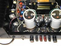
Here is what I did last summer to a DH-200. You can see a pair of 1,000 uF caps soldered in and behind the PCBs you can see the yellow polyprops (47 uF in this case). This followed advice read here to not put the smallest of the cascade at the filter caps but instead mount them close to the output devices.
I can tell you that this mod made a very noticeable improvement over the stock DH-200 and, in this instance, the buyer of the amp was agreeable to purchasing these extra parts and did not insist the amp remain "stock."
Good logic in your post. Over the last 2 years since I have monitored posts here the "cascading" of PS caps has been mentioned. I have the original Jung/Marsh article and do reread it now and then.
It is my understanding and recent improvements in technology make this cascading no longer necessary to keep down the impedance rise at higher frequencies and have very low ESR, DA, etc.
Here is what I did last summer to a DH-200. You can see a pair of 1,000 uF caps soldered in and behind the PCBs you can see the yellow polyprops (47 uF in this case). This followed advice read here to not put the smallest of the cascade at the filter caps but instead mount them close to the output devices.
I can tell you that this mod made a very noticeable improvement over the stock DH-200 and, in this instance, the buyer of the amp was agreeable to purchasing these extra parts and did not insist the amp remain "stock."
Attachments
- Home
- Amplifiers
- Solid State
- Hafler DH-200/220 Mods