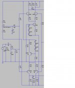
In the now 26 year old POOGE article by Jung & Marsh, they short out collector resistors R7 and R19 to change the original differential input pairs into an unbalanced operation. They do this without comment. I've noticed that in the earlier PASS designs he also does this, although most other designers (including Borebely)seem to leave these in a balanced (symmetrical?) configuration, i.e where the collector resitors on both transistors of the differential pair have the same value.
I don't see much difference from the simulations. Can anyone tell me what are the advantages to the unbalanced configuration?
Terry Ilardi
I don't see much difference from the simulations. Can anyone tell me what are the advantages to the unbalanced configuration?
Terry Ilardi
Their 240 watt amps are pretty nice. 4th order lowpass adjustable, and a 2nd order highpass at 20hz, along with soft clipping. I had a pair in my basement, but have since moved them up to the sealed 15" subs under my maggies. Very nice.
Downstairs, I now have a Crown XLS602 - the webgeek at Guitar Center screwed up, and they had 'em priced at $249.99. I'm adding two more subs, which will give me a two ohm load for each side. Gonna be interesting. I'd been thinking of running 'em with one of my DH-500s, but I decided that would really be a waste. Downside is that I'm having to add a 17hz active highpass filter, because first time I play Blackhawk Down or another bass-heavy flick at decent volume, I'll have four sub cones on the floor.
After the past few months, I've gotta say that too much wattage is almost enough... 255 each to my sides and rears, and the fronts and center all get 300.
Bogie
On another forum the consensus is: too much is too much! I look forward to the day I find out just what too much is!
I agree! I've had car systems and have home systems with what some would say is an INSANE amount of power. Yet those who hear them agree they sound awesome!After the past few months, I've gotta say that too much wattage is almost enough...
On another forum the consensus is: too much is too much! I look forward to the day I find out just what too much is!
Grey Rollins says:
Power switch for Hafler:Mouser part# 691-LTA201TRB/125N
I believe they are $3.80 ea. but I'm quoting from memory and may be off a bit in one direction or another. At any rate, they're not unreasonably expensive.
The switch does not install easily, but it can be done. The present switch can be removed by depressing the little "fingers" on the back side so the switch will slide out towards the front. I would suggest that after the wires are unsoldered that push-on connectors be installed so that when the new switch is put in place pushing on the connections is simple.
The proper switch should have its terminals numbered 1-2-3 (embossed in its plastic housing). Make sure you replace the wires to the proper numbered terminals. The switch hook up diagram can be found in the PDF file at WWW.HAFLER.COM (tech archive section).
The proper switch should have its terminals numbered 1-2-3 (embossed in its plastic housing). Make sure you replace the wires to the proper numbered terminals. The switch hook up diagram can be found in the PDF file at WWW.HAFLER.COM (tech archive section).
New guy
Hello all. I've read over the thread and found it to be a wealth of information. I have acquired an DH-200 and am beginning an overhaul/upgrade. I'll give a quick rundown of what I've fooled with so far before I get to the questions") .
.
I have replaced the main filter caps with 18,000uF each. Placed a 2.5 ohm 8 amp thermistor between the switch and fuse. Replaced C7 & C10 with 220uF low esr Panasonic caps and bypassed all electrolytics with .1 pp film/foil and replaced most film caps with pp.
I also changed C13 to 33pF between gate and drain on the N channel devises as per Mr. Borbely.
The input jacks have been replaced with some Cardas jacks and shielded twisted pairs running to the boards, the shields tied to chassis ground at input, each signal ground tied to star gnd via 5 ohm resistors. I am also replacing resistors with metal film.
I'm keeping the fuse in the feedback loop for now, just using 5A fuses. I don't like how fuses sound but I had a Dyna 410 weld a Scan Speak woofer at the far reaches of it's excursion once. Wish I had a fuse then. I'll try and rig up an A-B test for the fuse in and out of fb at a later date.
Now I head towards a few questions.
My project experience over the years has been mostly tubes so I'm a bit out of my depth with low impedance silicone gizmos. First I am intending on changing the input section C1 to 2.2uF pp, R2, R3 and C2 to 47K, 4.7K & 180pF. The input filtering with R3-C2 remains about the same. Will the higher input R cause any stability problems? Can I go to 100K? I have several tube pre-amps of my own design as well as my old stand-by SP-6B. (yes I still listen to vinyl on occasion) So 22k input is not what I need & 47K is a compromise.
Another area I'm unsure of is I have run a wire from star gnd to the chassis straight down in front of the bridge. Should the 680pF N channel drain to chassis gnd have a wire to star or is it sufficient as it is?
Also does anyone know a source for matched inputs, My DC offset is pretty far out being 35mV Rch & 71mV Lch. I don't see any other way to correct it.
Thanks in advance for any help. And apologies if I'm too long winded.
Hello all. I've read over the thread and found it to be a wealth of information. I have acquired an DH-200 and am beginning an overhaul/upgrade. I'll give a quick rundown of what I've fooled with so far before I get to the questions
. I have replaced the main filter caps with 18,000uF each. Placed a 2.5 ohm 8 amp thermistor between the switch and fuse. Replaced C7 & C10 with 220uF low esr Panasonic caps and bypassed all electrolytics with .1 pp film/foil and replaced most film caps with pp.
I also changed C13 to 33pF between gate and drain on the N channel devises as per Mr. Borbely.
The input jacks have been replaced with some Cardas jacks and shielded twisted pairs running to the boards, the shields tied to chassis ground at input, each signal ground tied to star gnd via 5 ohm resistors. I am also replacing resistors with metal film.
I'm keeping the fuse in the feedback loop for now, just using 5A fuses. I don't like how fuses sound but I had a Dyna 410 weld a Scan Speak woofer at the far reaches of it's excursion once. Wish I had a fuse then. I'll try and rig up an A-B test for the fuse in and out of fb at a later date.
Now I head towards a few questions.
My project experience over the years has been mostly tubes so I'm a bit out of my depth with low impedance silicone gizmos. First I am intending on changing the input section C1 to 2.2uF pp, R2, R3 and C2 to 47K, 4.7K & 180pF. The input filtering with R3-C2 remains about the same. Will the higher input R cause any stability problems? Can I go to 100K? I have several tube pre-amps of my own design as well as my old stand-by SP-6B. (yes I still listen to vinyl on occasion) So 22k input is not what I need & 47K is a compromise.
Another area I'm unsure of is I have run a wire from star gnd to the chassis straight down in front of the bridge. Should the 680pF N channel drain to chassis gnd have a wire to star or is it sufficient as it is?
Also does anyone know a source for matched inputs, My DC offset is pretty far out being 35mV Rch & 71mV Lch. I don't see any other way to correct it.
Thanks in advance for any help. And apologies if I'm too long winded.
Mike in florida,
As to the DC offset, I built a little PC board (attached it to the heatsinks) that injects a DC voltage into the front end (see attachement). I used a 10K trimpot here, if you do this try 5k, 10k is a little touchy). It has been described previously in this thread, an earlier Audio Amateur and is basically the idea used in the DH-220. I was able to get offset down to about .25mV in both channels (although I had also replaced the input transistors with transistors I had beta matched myself).
As far as the 680pf caps, I replaced them with .1uf ( per the DH-220) and left them connected to chassis ground at the heatsink. Seems to work fine. Hum is more or less inaudible (with input shorted, I need to bring my ear to less than 6 inches from the woofer to hear anything at all).
I also did a star ground configuration. I wanted to ask you why you returned signal ground through 5 ohm resistors. I have seen this before, I and don't understand why this is done. I didn't do this in my upgrade and while I am very pleased with the rsults I obtained perhaps I can do better.
I finished modifying my DH-220 this weekend (changed all passive components, and a few other parts) and was genuinely surprised that the modifications made as much difference as they did. I was very pleased with the result.
Terry Ilardi
Attachments
DH-200 impedance and DC offset
I do not understand why 22K input impedance is a problem in your system. Is it because your preamp open loop gain is reduced with input impedance of your power-amp? or you have multiple power amps so the load seen by your pre-amp is too low? or your pre-amp output impedance is too high?
22K gives a lower noise figure than with 100K but it may not be noticeable since all other sources of noise. But if you really need 47K you can do it but change R22 DC feedback to 47K also to avoid increasing DC offset at output. For R3 (2k2) you do not need to change it because you change R2. R2 and R23 should be equal for optimization (not taking into account your pre-amp output impendance though...) Increasing R3 to 4k7 also increases noise compared to 2k2.
since the 2N5401 and 2N5550 (Q1, 2, 5 and 6) are low cost you may buy several until you get matched devices. simply use a multi-meter with HFE (BETA) measurements of bjt transistors (or you can build a simple circuit on a "bread" board. Matching may be preferable to using a DC correction circuit if you can do it easily.
Good luck
mike in florida said:...First I am intending on changing the input section C1 to 2.2uF pp, R2, R3 and C2 to 47K, 4.7K & 180pF. The input filtering with R3-C2 remains about the same. Will the higher input R cause any stability problems? Can I go to 100K? I have several tube pre-amps of my own design as well as my old stand-by SP-6B. (yes I still listen to vinyl on occasion) So 22k input is not what I need & 47K is a compromise...
I do not understand why 22K input impedance is a problem in your system. Is it because your preamp open loop gain is reduced with input impedance of your power-amp? or you have multiple power amps so the load seen by your pre-amp is too low? or your pre-amp output impedance is too high?
22K gives a lower noise figure than with 100K but it may not be noticeable since all other sources of noise. But if you really need 47K you can do it but change R22 DC feedback to 47K also to avoid increasing DC offset at output. For R3 (2k2) you do not need to change it because you change R2. R2 and R23 should be equal for optimization (not taking into account your pre-amp output impendance though...) Increasing R3 to 4k7 also increases noise compared to 2k2.
mike in florida said:...Also does anyone know a source for matched inputs, My DC offset is pretty far out being 35mV Rch & 71mV Lch. I don't see any other way to correct it.
...
since the 2N5401 and 2N5550 (Q1, 2, 5 and 6) are low cost you may buy several until you get matched devices. simply use a multi-meter with HFE (BETA) measurements of bjt transistors (or you can build a simple circuit on a "bread" board. Matching may be preferable to using a DC correction circuit if you can do it easily.
Good luck
Ilardi,
Thanks for the reply and congratulations on completing your DH-220. There is a lot of satisfaction in tearing something apart and putting it back together much improved.
I believe I will add the offset trim to the circuit, easy enough to implement and I do have some multi-turn pots lying around unused. As for the 390pF caps on the output N channel MOSFETS it is my understanding that they are for waveform symmetry and 33pF on each device makes sense due to the inductance of the wires connecting the MOSFETS. The value of 33pF and the placement between gate and drain as suggested by Mr. Borbley seemed a wise choice since he designed the amp.
I have run a wire from c18 chassis ground at the heatsink to a lug I placed in front of the rectifier. Since the heatsinks are fastened to the main chassis with sheet metal screws I thought running a wire to a central point would be a good idea. What I'm unsure about is whether or not to tie the chassis to 0v / star ground. I have done it in a way that will be easy to A/B test once the amp has settled in and the ears will determine if I remove it.
My choice of the 5 ohm resistors at the input was carefully determined by searching through my boxes and finding 5 ohm being the smallest I had under 2 watt. My reason for keeping the inputs referenced above the chassis is that I tend to look at the chassis as RF shield (also antenna) which gets back to not tying the chassis directly to star ground.
I am by no means an electrical engineer just someone who trys to not let the smoke out too often and make things sound good in the process.
Mike
Re: DH-200 impedance and DC offset
The simple explanation is tubes. More specifically almost all my gear is vacuum tube. Two CD players are tube from the DAC on out, my main DAC is a CAL Audio Sigma. Preamps are all tube.
So all signals go through caps and I find all caps to be audible. The larger the cap the more noticeable they become.
I realize I am in dangerous territory on the solid state forum. Some would even say I belong in the tin foil hat crowd. But heck we are all probably a little nuts.
I was a fledgling tinkerer when Marsh and Jung came out with there work on caps in Audio and it had me wildly bypassing everything in sight.
With tube gear at least, I find anything above 1uF to be less than satisfactory, I will generally parallel 2 .47's.
I try to use as small as will get me the bandwidth I want and no larger.
Output impedance is a factor. To me it seems even with 600 ohm output impedance tube gear sounds more open with higher impedance loads.
With lower impedance loads the soundstage will first loose height then narrow and finally become very shallow. The liquidity also diminishes.
Tubes are High impedance devices that can be made to work into a heavy load but they don't sound best there to my ears.
Thanks, That is why I am here. No solid state design smarts. I completely missed the feedback value. The increased offset would have driven me nuts.
Regards to noise, the resistors are now all metal film so I gain something there at least.
I can match tubes but not BJT's. I have no meter do do so. I could rig up a way to current match but I was trying to take the easy way out and hope there was a source of matched parts.
I do have some sockets so I could breadboard a tester.
From your experience could you recomend a number to order for testing? Thanks
fab said:
I do not understand why 22K input impedance is a problem in your system.
The simple explanation is tubes. More specifically almost all my gear is vacuum tube. Two CD players are tube from the DAC on out, my main DAC is a CAL Audio Sigma. Preamps are all tube.
So all signals go through caps and I find all caps to be audible. The larger the cap the more noticeable they become.
I realize I am in dangerous territory on the solid state forum.
Some would even say I belong in the tin foil hat crowd. But heck we are all probably a little nuts.I was a fledgling tinkerer when Marsh and Jung came out with there work on caps in Audio and it had me wildly bypassing everything in sight.
With tube gear at least, I find anything above 1uF to be less than satisfactory, I will generally parallel 2 .47's.
I try to use as small as will get me the bandwidth I want and no larger.
Output impedance is a factor. To me it seems even with 600 ohm output impedance tube gear sounds more open with higher impedance loads.
With lower impedance loads the soundstage will first loose height then narrow and finally become very shallow. The liquidity also diminishes.
Tubes are High impedance devices that can be made to work into a heavy load but they don't sound best there to my ears.
fab said:
but change R22 DC feedback to 47K also to avoid increasing DC offset at output. For R3 (2k2) you do not need to change it because you change R2. R2 and R23 should be equal for optimization (not taking into account your pre-amp output impedance though...) Increasing R3 to 4k7 also increases noise compared to 2k2.
Thanks, That is why I am here. No solid state design smarts. I completely missed the feedback value. The increased offset would have driven me nuts.
Regards to noise, the resistors are now all metal film so I gain something there at least.
I can match tubes but not BJT's. I have no meter do do so. I could rig up a way to current match but I was trying to take the easy way out and hope there was a source of matched parts.
I do have some sockets so I could breadboard a tester.
From your experience could you recomend a number to order for testing? Thanks
Re: Re: DH-200 impedance and DC offset
I have already ordered NPN bjt that have about the same HFE but it was different from the requited HFE for PNP for matching. There is no magic recipe I believe to get matched bjt for complementary part numbers. Sometimes it is better to get several different production lot numbers to increase the chance to get what you need. So it does not depend on the quantity.
In fact, you may have only one or two of your 4 bjt diff input stage that may be replaced for DC offset reduction purpose.
You can try this site http://www.borbelyaudio.com/pics/Compprice.pdf
to get matched parts.
I was able to get lower than 5 mv DC offset for the 4 bjts with HFE matched within about 10% to 15%
mike in florida said:
...I can match tubes but not BJT's. I have no meter do do so. I could rig up a way to current match but I was trying to take the easy way out and hope there was a source of matched parts.
I do have some sockets so I could breadboard a tester.
From your experience could you recomend a number to order for testing? Thanks
I have already ordered NPN bjt that have about the same HFE but it was different from the requited HFE for PNP for matching. There is no magic recipe I believe to get matched bjt for complementary part numbers. Sometimes it is better to get several different production lot numbers to increase the chance to get what you need. So it does not depend on the quantity.
In fact, you may have only one or two of your 4 bjt diff input stage that may be replaced for DC offset reduction purpose.
You can try this site http://www.borbelyaudio.com/pics/Compprice.pdf
to get matched parts.
I was able to get lower than 5 mv DC offset for the 4 bjts with HFE matched within about 10% to 15%
mike in florida,
Take a look at fab's post #200.
"You have perfectly understood. Only the K134 that is right. In fact if you check latest Erno's designs on the Borbely audio web site you will see that it is the case. And Erno confirmed that the g-d cap should have been used for the DH-200/220 and others too. However, the g-s cap is not that bad at all but as Erno has indicated the g-d cap improves stability even better. "
As I understood it, the 390 pf g-s cap is removed and the 33pf g-d cap(s) used istead. I further replace the 680pf C18 cap with a .1pf cap per the DH-220 schematic.
I have tied everything to chassis ground,(well first a star ground but I have tied the star ground to the chassis). It seems like a good idea, however, to tie the heatsink lug to chassis ground since the chassis-heatsink connection is suspect.
I think a need a lesson here about RF shielding. Why does holding the input ground above chassis ground improve shielding? Thanks.
Terry Ilardi
Re: DH-200 impedance and DC offset
These new fangled solid state device are getting more interesting all the time I hadnt realized that 10% or so matching was all that was needed to correct the offset.
I went out today and bought a cheap meter that does hfe testing. Good old Harbor Freight tools, reg $39 on sale for $19.
It turned out I needed it more than I thought. After the first stage of my mods were done I put her back together last night and brought it up on a variac. The right channel output was at full -DC.
After pulling the board off and looking for solder bridges or other screw-ups I noticed the heatsink on Q12 moving around. I pulled on it and out it popped. all three leads nice and grey. Don't know how it worked before.
I hope the MSOFETS are OK I did a quick G to S and G to D check and all were infinite R so my fingers are crossed.
Later tonight I'll place a web order with Mouser and Digi-Key so I get different lots of input transistors and I'llget to matching.
I'm having fun with this and the more I look at how this was designed the more I appreciate it. Thanks for your help.
fab said:
I was able to get lower than 5 mv DC offset for the 4 bjts with HFE matched within about 10% to 15%
These new fangled solid state device are getting more interesting all the time
I hadnt realized that 10% or so matching was all that was needed to correct the offset.I went out today and bought a cheap meter that does hfe testing. Good old Harbor Freight tools, reg $39 on sale for $19.
It turned out I needed it more than I thought. After the first stage of my mods were done I put her back together last night and brought it up on a variac. The right channel output was at full -DC.
After pulling the board off and looking for solder bridges or other screw-ups I noticed the heatsink on Q12 moving around. I pulled on it and out it popped. all three leads nice and grey. Don't know how it worked before.
I hope the MSOFETS are OK I did a quick G to S and G to D check and all were infinite R so my fingers are crossed.
Later tonight I'll place a web order with Mouser and Digi-Key so I get different lots of input transistors and I'llget to matching.
I'm having fun with this and the more I look at how this was designed the more I appreciate it. Thanks for your help.
re: Caps and grounds
ilardi,
Regarding the gate-drain caps I will refer to the DC-50 amp which is not too far from the DH-200 and the use of caps on each N channel MOSFET.
http//www.borbelyaudio.com/home_theater.asp
Wire in a design is an LRC network granted very small values of C & L but inductance still concerns me when C in pico-Farad values are used.
It just seems reasonable to me to place a cap on each device that you are trying to tune and not shotgun the whole output.
Holding the input above chassis does nothing to improve shielding. My apologies if I was unclear, my communication skill are sub-par at best.
The chassis acts as an RF shield, but the whole amp chassis, circuitry, etc. can also be an RF antenna. All this is bad for audio.
A common practice and for good safety reasons is to tie the chassis to the groung wire (neutral) of a 3 wire power cord. Protection in the outside chance of a transformer winding shorting or other shorts to the chassis since there is the potential for lethal voltages to be present on the case of the equipment.
Now if you have a scope, run a wire to a nearby water pipe as a ground, next place the probe on the neutral or ground of a electrical outlet.
A good place to do this is at the water heater. What you will find is that the so called ground in your power outlet is alive with a wide frequency spectrum. Grunge! All of this is AC same as the signal input though at a much lower level. The last thing you want is for this garbage to insert itself into the signal.
The DH-200 as well as most amps have a split power supply and between positive V+ and V- is 0 volts or power ground, not earth ground which the chassis is at. One fairly common practice was to tie the chassis to the circuit with a disc cap .1 or so. It references the chassis to 0 volt but not to DC. Back to the DC-50 which is similar to the DH-200 the chassis is DC tied to power through a resistor and diodes so noise on the chassis is .6 volt below the signal or noise floor of the amp.
Try to think of the input as needing to be rock-solid as to gnd. if 0v is modulated by AC on it then the signal in a loose sense follows it intruding on very low level detail. Keeping 0 volt DC and chassis separated has it's merits. I make this way more complicated than it is, but as I said my communication skills are lacking.
As I mentioned The wire I have run to chassis gnd is very accessible quickly removed for the purposes of AB testing at a later date.
Even though I use a simple AC mains power filter when I audition a circuit modification or new design, when I get serious I do it at 3 or 4 in the morning when the AC power is cleanest. The difference is clearly audible. I mentioned before I was not an engineer. I think I just proved it.
My apologies if I strayed too far off topic for this thread.
Mike
Mike,
Your communication skills are fine. I'm going to leave my Hafler as it is now, and wait for the results of your listening test (as to the input grounding issue) if you can be persuaded to report them here. I've spent to much time working on this amp before making any more changes. I want to listen to it before I open it up again!
I also adopted the DC-50 configuration of the caps, more or less. I put 33pf g-s caps on each of the 134s but I only put one .1uf caps on the sources of the pairs of the 134s and 109s. It was getting cramped on the heatsink.
As to your not being an engineer, neither am I. But sometimes I like to play at being one.
Terry Ilardi
DC rail on output
The investigation continues. I'll be glad when I finally get a chance to hear the upgrades to the DH-200. So far though I have not tracked down the source of the voltage on the right channel. It has the full negative rail less 2 volts.
I've gone over the board many times looking for solder bridges or bad traces to no avail. It was fine before I replaced the electrolytics and added bypasses. Replaced some resistors with metal film but each resistor was checked for value first. And I am usually very carefull with my work. So I am stuck as to where I screwed up.
I checked the drivers Q12 & Q13, they're OK. Also checked D14 on the outside chance it shorted. I pulled 1 pair of MOSFETs at a time to see if the problem was one of those and no change. I'm slowly working my way back. Tonight I'll get to Q8,Q9 and Q10, Q11 and whatever else seems to pop up.
This is probably all an exercise in futility trying to prove to myself that a no longer available MOSFET is bad. One can wish.
(Hmmm, 80,000uF 100w mono amp)
Mike,
From your description it seems the problem to be in the Mods that were added. Best to go slowly on them, that way you can make progress to determine what is indeed an improvement. Try to go back to the original configuration and go from there. My quick guess is to focus on the low esr caps used as a bypass in the negative feedback connection up front in the diff amp. Low esr sometimes also results in higher leakage current. High leakage current at the input can cause DC offsets to rail in operation.
From your description it seems the problem to be in the Mods that were added. Best to go slowly on them, that way you can make progress to determine what is indeed an improvement. Try to go back to the original configuration and go from there. My quick guess is to focus on the low esr caps used as a bypass in the negative feedback connection up front in the diff amp. Low esr sometimes also results in higher leakage current. High leakage current at the input can cause DC offsets to rail in operation.
- Home
- Amplifiers
- Solid State
- Hafler DH-200/220 Mods