Hi Veysel,
Interesting. I just bought a Luxman C-02, M-02 and T-3 tuner as a set. The actual units are very good looking. One thing that you have done, which I wish that Luxman had done, was to use a conventional heat sink. The M-02 uses a Freon type heat sink where the heat is transferred by the fluid to the fins located a few inches away. This allowed for a reasonably flat case design, but it also tends to run hotter. Heat is unwelcome.
Your design should be stable and last for many, many years.
-Chris
Then don´t run it, Chris. I´ve seen similar comments around this forum. Is that supposed to sound as a critic to those that do use simulators, to diminish what they do?
Several respectable guys in this forum, which use both simulators, as well as paper and calculators, had provided with high quality diy designs. And they found, when the prototype was built and tested, that the measurements were almost the same, with errors within what you see on any service manual.
Why don´t you give it a try? I´m an old fart too, close to 70, and I´m very happy I did.
Carlos
Hi Carlos,
Nope, I'm just admitting that I don't know how to run the simulators, which is my failing. I can't understand how you could read anything else into that.
Once I have the time (whenever that will be), I will probably give it a whirl. But since I generate a schematic in my PCB layout program, laying it out again in a simulator looks like I'm repeating my work. I'm very lucky in that when I lay out a PCB, the device usually works and only needs component tweaking. Sometimes the circuit works perfectly (this gets more common the older I get). Some advantage in being an old fart, but younger that you are.
-Chris
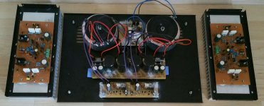
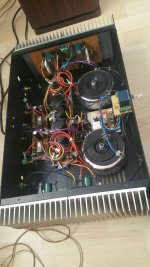
Yes why not build it, the M-02 is a very nice amplifier ")
Have you made a schematic for your rebuild project? Is it working well?
I have two of the M-02 amps actually, one unit is out of service for renovation. I am moving the power resistors to the topside of the PCB, to give better thermal balance, and improving a few other things - like changing the speaker terminals. But I think the original heatpipe cooling works at least as well as a typical conventional passive heatsink. Only problem was (is), that Luxman made the matching Preamp (C-02) too small to stack the M-02 on top of it. So most people put the preamp on top of the M-02, which of course blocked the heat rising out of it... Even so, many have survived 35 years so far, despite these terrible thermal conditions.
Chris,
My deep and sincere apologies about my interpretation of what you said. You may find it strange, but many people (like John Curl) sort of snobbed many times simulations and people that got to conclusions from them. If I hadn't read such comments myself, I might be tempted to not believe anyone who said they existed.
You raise a good point on where you generate your schematic, which will later become a pcb. Some programs have some sort of simulations, but they are not as popular as LTS.
Of course you need to prototype things, that's obvious. Finding good parts models is the key, but now there seem to be many around.
On the case of that Luxman M02 sim I can't get it to amplify, so I wonder what schematic Veysel used. Mine was based on that on the service manual, but I took away the output protection circuit.
Carlos
Here's the sim for the M02 clone I did, using available parts, particularly for the input fet.
But I'm curious about this working clone, particularly on how you solved the DC offset issue. A DC servo would be necessary with no NFB cap.
But I'm curious about this working clone, particularly on how you solved the DC offset issue. A DC servo would be necessary with no NFB cap.
Attachments
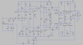
Yes, I forgot the DC offset is controlled by the 2uF & 4M7 combo.
Legit 2SC2705 are hard to find these days, only fakes. SC1845 Are a good replacement.
According to a paper by Linkwitz, 10uH is a better choice for output inductor. In any case is something you could try and listen.
Yes, I would use a volume pot, that's why I put 470K.
Did you have problems with thermal compensation? Isn't it the bias transistor over output transistor or heatsink that keeps things stable?
I can sim three diodes instead of LEDs to see how they behave, but I think it's the actual audio quality that should define what to use.
On later amps, like the 504, Luxman did use three diodes on VAS.
- Status
- This old topic is closed. If you want to reopen this topic, contact a moderator using the "Report Post" button.
- Home
- Amplifiers
- Solid State
- Luxman m02 lets rebuild