Can you say more on this ?
Cause and effect reversed. I said a while ago look at the inverting configuration, less confusion. Would you say a bipolar transistor is primarily a current amplifier and only beta matters?
Last edited:
Feed a fast rise/fall time square wave into a CFA (so t5here are lots of HF harmonics) and monitor the DB output current. It 'spikes' on the edges due to its COD behaviour. In other words, the loop is driving the HF content (harmonics) hard in order to replicate the square wave as accurately as possible within the limitations of the available drive current from the feedback resistor and any (compensation) capacitance connected to the 2nd stage input.
In a classic MC VFA, this does not happen because the peak current is limited by the tail current, so it instead slews. To mitigate this, you have to degenerate the input pair or bandwidth limit the input signal or a combination of the two (not an exhaustive approach, but it covers most cases)
Of course, there are ways around the slew rate limitations in VFA's, but if you want to get to the core of what a CFA is and does and what differentiates it from a VFA, its how I've described it above.
Feed a fast rise/fall time square wave into a CFA
My point with the inverter, instantaneously the output does not move and Vin over Rg goes right into the -input and is mirrored to Ccomp..
Certainly not. Vbe matters.Cause and effect reversed. I said a while ago look at the inverting configuration, less confusion. Would you say a bipolar transistor is primarily a current amplifier and only beta matters?
Feed a fast rise/fall time square wave into a CFA (so t5here are lots of HF harmonics) and monitor the DB output current. It 'spikes' on the edges due to its COD behaviour. In other words, the loop is driving the HF content (harmonics) hard in order to replicate the square wave as accurately as possible within the limitations of the available drive current from the feedback resistor and any (compensation) capacitance connected to the 2nd stage input.
In a classic MC VFA, this does not happen because the peak current is limited by the tail current, so it instead slews. To mitigate this, you have to degenerate the input pair or bandwidth limit the input signal or a combination of the two (not an exhaustive approach, but it covers most cases)
Of course, there are ways around the slew rate limitations in VFA's, but if you want to get to the core of what a CFA is and does and what differentiates it from a VFA, its how I've described it above.
Sure, this can be true, but how does this justify it being called a CFA as opposed to perhaps a great VFA? By what mechanism, not by variant characteristics everyone seems clear on the differences, is it a CFA?
Sure, this can be true, but how does this justify it being called a CFA as opposed to perhaps a great VFA? By what mechanism, not by variant characteristics everyone seems clear on the differences, is it a CFA?
??
VFA's don't behave like a CFA other than Vo = kVi (or Io = kIi, or Io = kVi, or . . . . etc etc) where k is the amplification factor in the simplest context. What we are trying to establish how a VFA or CFA arrives at Vo=kVi by fundamentally different topological mechanisms and dispel the notion that a CFA is a VFA.
If this is your point is that because the input is voltage and the output is voltage therefore it must be a 'VFA' then we are simply getting back into semantics.
If we are to progress this discussion, you have to separate the canonical feedback forms from what you feed into the non-inv and invert-inputs. They are complementary, but two different things.
Further, its very easy to muddy the discussion by talking about the grey area where there is some overlap in the performance characteristics (e.g. high open loop gain CFA and high open loop VFA), so lets discuss the topologies in their classic forms - LTP front end MC compensated VFA and a bog standard DB input CFA. We can talk about what's great and not great, and the performance overlaps, later once we've sorted out what really constitutes a VFA and a CFA!
Last edited:
My point with the inverter, instantaneously the output does not move and Vin over Rg goes right into the -input and is mirrored to Ccomp..
Yes - agreed - I see your point on this.
My opinion is to just concentrate on the Dual Injection Technique itself.Could you please state the rules for using Middlebrook's DIT outside of a loop? Certainly there are valid tests that can be applied without global loops. But let's be careful that we don't start another (at least partially) nomenclature-based dispute!
Making Rg and Rf changeable makes the whole thing more universal.
In case of Rf=Rg=1k, you have the Middlebrook variant.
But in your case for the uA741/LT1001 the model could show that it stayed a VFA despite an Rf of 10k and an Rg of 100 Ohm and did not become a CFA.
Also in Ians case I could use a Rf of 10Gig (equals open loop) and an Rg of 100K and DIT showed that LT1395 still behaved like a CFA, just because the inverting input could sink and source current into the 100K Rg resistor, being replicated into Z(s) and showing up as a voltage to the output.
The LT1364 came also out clearly as a VFA and not a CFA , and the two circuits from Herve were correctly classified as CFA's.
And in several of these tests different values for Rf and Rg could be used.
Since slewing on demand, not covered by DIT, is not exclusively restricted to CFA, I would say that this DIT model with variable Rf and Rg is a valuable tool in determining what we have at hand.
It would be nice if, after these completely different tests all with positive outcome, we could find consensus on the discrimination quality of this measuring tool between CFA and VFA.
Hans
Hans, I think the technique is interesting, but we already know there is an overlap in some of the characteristics as I alluded to above. To my mind the the overlap arises because the performances become similar - not because there is a fundamental change in operating principle.
I wouldn't matter if it was. Their argument is flawed on a more basic level.
Yes, it is flawed. Just trying to reach them however I can.
??
VFA's don't behave like a CFA other than Vo = kVi (or Io = kIi, or Io = kVi, or . . . . etc etc) where k is the amplification factor in the simplest context. What we are trying to establish how a VFA or CFA arrives at Vo=kVi by fundamentally different topological mechanisms and dispel the notion that a CFA is a VFA.
Exactly... but why are we necessarily dispelling the notion that a CFA is a VFA or otherwise, or not to let it be whatever it is? Why is it that we need to address any form of AC signals at any frequency... as opposed to beginning with a DC study.
Is it generally held that no-one can figure out the characteristic behaviour of a VFA or CFA under DC conditions?
Is it that truth can only be derived from the seemingly extremely more complex behaviour under AC conditions?
Is it taken for granted that under DC conditions these devices can't be characterized as VFA's or CFA's?
The point is why is anyone bothering with AC artifacts, other than for the propose of proposing some characteristic advantage in some way. That is my point.
Hi Chris,
Let me try to answer this from my side.
You found an (unexpected ?) discrepancy in the transimpedance.
Next step made by you was to suggest to make the Early Effect responsible for that.
To start with, I invested quite some time checking all your findings, to which I agreed.
Then I changed your model by replacing Q1 to Q4 to ideal transistors with a parametrised resistor in parallel to simulate Ro.
With a value of ca. 140K for Ro, I could exactly replicate your measurements with the 2N3904/3906 model.
Although I agreed with you on your findings and your conclusions, I failed to see the relevance of this phenomena.
Thats one of the reasons why I also made the DIT model, to investigate to what degree this Early Effect had any importance on the working of the CFA.
The DIT simulation with your very model in completeness with all transistors, confirmed my suspicion that apart from some insignificant effect on loop gain, the Early Effect could be put aside as a complete unimportant issue.
But despite all my efforts, there were still many postings from you where you kept asking "I ask again for the umpteenth time: Why is ic/vbe different from I q / (k T)?"
The question was already answered with Ro but you kept on asking.
It must be quite obvious that I invested a significant amount of time in checking, building models and so on to answer your question and to show the irrelevance of the matter.
But for some reason it keeps popping up over and again.
That's why I suggested to close this book, without the intention of being unfriendly.
Hans
Hans, Thanks much for your reply.
I must have missed your much earlier agreement about the Early effect for some reason. I kept asking for a reply because I didn't see it!
The point was always, and only, this: that the transistor not acting anywhere near like a pure transconductor has enormous relevance - if your entire theory of CFA voltage feedback is based on it. Otherwise, as you and Scott have said, it has almost none at all; the circuit compensates almost imperceptibly for various ratios of vbe gm to vce / Ro.
It is a shame that a communications problem led to all this effort and some significant acrimony. Scott was right - this forum challenges communication. I apologize for my contribution to the problem. I hope and expect thatwe can finally put this to bed. The only bright side for me is that I learned an interesting detail about transistor operation in a certain location within a high gain loop.
My opinion is to just concentrate on the Dual Injection Technique itself.
Making Rg and Rf changeable makes the whole thing more universal.
In case of Rf=Rg=1k, you have the Middlebrook variant.
But in your case for the uA741/LT1001 the model could show that it stayed a VFA despite an Rf of 10k and an Rg of 100 Ohm and did not become a CFA.
Also in Ians case I could use a Rf of 10Gig (equals open loop) and an Rg of 100K and DIT showed that LT1395 still behaved like a CFA, just because the inverting input could sink and source current into the 100K Rg resistor, being replicated into Z(s) and showing up as a voltage to the output.
The LT1364 came also out clearly as a VFA and not a CFA , and the two circuits from Herve were correctly classified as CFA's.
And in several of these tests different values for Rf and Rg could be used.
Since slewing on demand, not covered by DIT, is not exclusively restricted to CFA, I would say that this DIT model with variable Rf and Rg is a valuable tool in determining what we have at hand.
It would be nice if, after these completely different tests all with positive outcome, we could find consensus on the discrimination quality of this measuring tool between CFA and VFA.
Hans
I believe you were talking about using Middlebrook's DIT test open loop. Am I correct? (Maybe not - communication does not appear to be one of our strengths.
) If so, I was asking for a procedure for how you'd do this. It had nothing to do with the values of Rf and Rg as long as Rg was not zero and Rf was not infinite. That is, as long as we are talking about closed loop operation.On another note, here's my problem with using Middlebrook to name the circuit rather than to simply determine the predominant form of feedback once a particular feedback network is employed:
You and I buy the same ICs, but we connect them to different feedback networks. The idea that I bought a CFA and you bought a VFA will cause more rather than less confusion.
Last edited:
I do not think these mechanims are fundamentally different. I hope to be able to explain why later.What we are trying to establish how a VFA or CFA arrives at Vo=kVi by fundamentally different topological mechanisms and dispel the notion that a CFA is a VFA.
Sorry, but I missed the postings with the points you are referring to.Hans, I think the technique is interesting, but we already know there is an overlap in some of the characteristics as I alluded to above. To my mind the the overlap arises because the performances become similar - not because there is a fundamental change in operating principle.
Maybe you could be so kind to repeat these for me.
When you mean that VFA and CFA are becoming similar in characteristics, I fully agree, but nevertheless they still can be divided in one of the two categories, like the LT1364 being a VFA making full use of CFA know how, but nevertheless still being a 100% VFA.
Is that what you could possibly mean ?
Hans
I'm surprised no one wants to try the design challenge. Use the stock 3904/3906 models that come with LTspice and make a 20dB gain line stage from a 20K pot that drives 600 Ohms at 2V rms. To make it simpler just use 19kHz and 20kHz IMD (2V rms total) as the metric. Maybe set a supply current limit of 10mA and allow ideal sources to set up the bias, but real transistors in the signal path. Tracing out where the distortion comes from is a useful exercise.
Exactly... but why are we necessarily dispelling the notion that a CFA is a VFA or otherwise, or not to let it be whatever it is? Why is it that we need to address any form of AC signals at any frequency... as opposed to beginning with a DC study.
Is it generally held that no-one can figure out the characteristic behaviour of a VFA or CFA under DC conditions?
Is it that truth can only be derived from the seemingly extremely more complex behaviour under AC conditions?
Is it taken for granted that under DC conditions these devices can't be characterized as VFA's or CFA's?
The point is why is anyone bothering with AC artifacts, other than for the propose of proposing some characteristic advantage in some way. That is my point.
I think you can explain how they work differently at DC - they are fundamentally not the same.
However, the point made by others is that at DC you do not see in the performance any of the defining characteristics of either topology that you see at HF - namely independence of gain vs closed loop bandwidth (CFA) vs constant gain bandwidth (VFA), or COD (CFA) vs slew limited behaviour (VFA).
There of course is still the small matter of claiming a CFA is a VFA because it still 'compares voltages' at its inputs. However, that's neither here nor there because the voltage at the CFA inverting input requires a current to flow across (Rg + re) to develop a voltage at the - input that equals the non-inverting input (lets assume DC for this immediate discussion to keep it simple) and this current, as Scott has pointed out, can flow into and out of the inverting input. I am afraid no VFA does this - the inverting input impedance in the ideal case is infinite and the feedback resistors can therefore take on a very wide range with little or no effect on performance. In a CFA, if the feedback network (Rf and Rg) absolute values are too high, it ceases to operate.
Hi Chris,I believe you were talking about using Middlebrook's DIT test open loop. Am I correct? (Maybe not - communication does not appear to be one of our strengths.
On another note, here's my problem with using Middlebrook to name the circuit rather than to simply determine the predominant form of feedback once a particular feedback network is employed:
You and I buy the same ICs, but we connect them to different feedback networks. The idea that I bought a CFA and you bought a VFA will cause more rather than less confusion.
We are seemingly very good in miscommunication, but I take full and complete responsibility for that, but don't worry, at the end we solve all this.
Your control over the English language is so much better than mine.
In this case when understanding you correctly, your question is: why using DIT when different use may only cause more confusion.
But wasn't the whole idea of this thread to get a finger behind this CFA / VFA thing, does it really mean something or is it just some commercial invention ?
To come back to the first line of your posting: no, I was not referring to Middlebrooks open loop test.
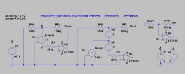
I even would like to avoid the name Middlebrook to prevent misunderstandings and only use the word DIT, but as you can see in the Image, when making Rf and Rg 1K, you have the Middlebrook version.
I was all the time using the set up from the image below, only Rf and Rg were changed depending on the circuit being tested.
Here it is configured for doing an open loop test with the LT1395 CFA with Rf 10Gig and Rg 100k, the outcome of which was shown in #1338.
In the explanation in #1338, the names of Rf and Rg were accidently switched, but the test itself and the image being produced were O.K.
Hans
Attachments
I'm surprised no one wants to try the design challenge. Use the stock 3904/3906 models that come with LTspice and make a 20dB gain line stage from a 20K pot that drives 600 Ohms at 2V rms. To make it simpler just use 19kHz and 20kHz IMD (2V rms total) as the metric. Maybe set a supply current limit of 10mA and allow ideal sources to set up the bias, but real transistors in the signal path. Tracing out where the distortion comes from is a useful exercise.
where is the circuit to do this exercise?
THx-RNMarsh
where is the circuit to do this exercise?
That's the exercise, it's up to you.
- Home
- Amplifiers
- Solid State
- Current Feedback Amplifiers, not only a semantic problem?