
Originally Posted by forr
It is only a common base stage for 0V at the non-inverting input.
But this input receives a voltage signal.
It does not have to be zero. In a common base stage, the voltage at the base is the reference ('common' ) for the input signal at the emitter. But that does not mean it can not have an independent input signal so that the final output is a function both of the voltage at the base and the current at the emitter. It is still a common base stage.Jan
The attachment shows a circuit that JM Plantefève proposed. It is a single polarity version of the topology currently called CFA and is extremly explicit.
If you see Q5 as common-base in this design, it can also be seen as playing the roles of an emitter-follower and of a common-emitter with emitter-degeneration.
However, I am always a bit reticent to firmly name the configuration of transistors as it often happens to be a combination of two or three configurations.
Anyway, what is indisputable, is that the collector current is driven by the base-emitter voltage. Looking at how the base voltage and the emitter voltage are built is the best starting point for analysing linear circuits such as those considered in this thread.
.
Last edited:
These folks are unhappy with an established term based on a dubious analysis. They find that it is an excellent thing for people studying analog electronics if they are aware of the part of the controversy which concentrates on the topology named CFA and the way its associated circuit works.I'm not sure where this controversy arose but I think it was from folks with narrow ultra-academic ways at looking at these things, i.e. why do they care?
- Mr. Jung talks about the "relative constant closed loop bandwidth, regardless of the closed loop gain" which is again correct, but is once again the property of a particular circuit topology (which could be also called "diamond buffer input stage topology" instead of "CFA", but which would be of course way to complex for the marketing departments). It would be also correct and relevant to add "for a certain range of closed loop bandwidths". The property holds indeed for closed loop gains of, say, 0...12dB but no longer holds significantly for closed loop gains of, say, 30...40dB.
- I absolutely agree with MK that the CFA topology is simply moot when it comes to audio, it is just another buzzword. Set aside that only a few years ago, the CFA topology was chastised right here on DIYAudio as having a "horrible screechy sound", the usual high closed loop gain required in audio amplifier (20-30dB) makes any CFA topology advantages blur away, while the high slew rate (as a result of the current on demand property) is simply useless. Nobody was ever able to prove mathematically or experimentally, under controlled conditions, that more than 1V/uS per 1V of peak (audio) output is required.
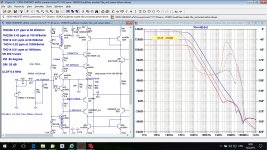
I don't understand why you are against "CFA" used in audio output amplifiers.
From attachment you can see that you are wrong in both of your above statements, relative constant closed loop bandwidth, regardless of the closed loop gain not holds for CLG from 30 to 40 dB, and not possible very low distortion. You would say it's simulated, but even ten times worst still very good result.
Damir
Attachments
However, I am always a bit reticent to firmly name the configuration of transistors as it often happens to be a combination of two or three configurations.
Anyway, what is indisputable, is that the collector current is driven by the base-emitter voltage. Looking at how the base voltage and the emitter voltage are built is the best starting point for analysing linear circuits such as those considered in this thread.
.
I agree with the first point.
I do not agree with your 2nd, which btw seems to contradict the first point.
")
I can dispute that, and I can do that right here and now. It is abundantly clear that the collector current of a BJT is driven by the base current. Or the emitter current. Or.... Your point 1 again.
Jan
Lets go from the other side, let us assume your just developed the very first ' CFA' opamp, and the marketing dept gives you free reign to name it. You want to distinguish it from the current crop of ' VFA' opamps.
How would YOU name the new kid on the block?
A way to distinguish the two main design variations is useful. We can also divide the opamp population between ' FET input' and ' BJT input' groups. Now we have 'common base feedback' and 'common emitter feedback'. I use this terminology loosely, this is not my main point, but since you haven't named your creation yet, I am making do.
What would be a cool name that marketing can exploit?
Jan
What shall we call an amplifier that actually has current feedback then?
Any feedback is a power feedback. I.e. we take some power from output and apply to input, never only voltage nor only current. It is not magic Zen with one hand clapping, it is a plain dumb physics. No other hand, no clap, sorry!
Was it something new invented when opamps got low inverting input impedance in respect to non-inverting input? Not at all!
Take some old rusted vacuum tube amp and look how feedback goes to cathode of an input tube of a power amplifier...
What shall we call it? I don't know. An amplifier, I guess?
I'm not sure where this controversy arose but I think it was from folks with narrow ultra-academic ways at looking at these things, i.e. why do they care?
Academy of marketing?
"No name, no sales!"
Originally Posted by forr
However, I am always a bit reticent to firmly name the configuration of transistors as it often happens to be a combination of two or three configurations.
Anyway, what is indisputable, is that the collector current is driven by the base-emitter voltage. Looking at how the base voltage and the emitter voltage are built is the best starting point for analysing linear circuits such as those considered in this thread.
I agree with the first point.I do not agree with your 2nd, which btw seems to contradict the first point.
I can dispute that, and I can do that right here and now. It is abundantly clear that the collector current of a BJT is driven by the base current. Or the emitter current. Or.... Your point 1 again.
The Ebers-Molls model and a greatly experienced person like Douglas Self let us to think that, for the practice of circuits, the bipolar junction transistor has to beconsidered as a voltage-operated device.
What counts is the base-emitter voltage, or Vbe.
[...Current] Ib is normally just a nuisance.
(Douglas Self 'Small Signal Audio Design' Second Edition Focal Press, page 78)
This already happened with valve amplifiers having negative feedback applied to the cathode of the input stage. What was the universally accepted name of the feedback topology then ?Lets go from the other side, let us assume your just developed the very first ' CFA' opamp, and the marketing dept gives you free reign to name it. You want to distinguish it from the current crop of ' VFA' opamps. How would YOU name the new kid on the block?
Terms shortly decribing the circuit rather than the supposed way CFA works would be cool. Maybe "Series Push-Pull Input stage" or already often used "diamond".A way to distinguish the two main design variations is useful. We can also divide the opamp population between ' FET input' and ' BJT input' groups. Now we have 'common base feedback' and 'common emitter feedback'. I use this terminology loosely, this is not my main point, but since you haven't named your creation yet, I am making do.
What would be a cool name that marketing can exploit?
If it is a technical discussion, there are only and only feedbacks:
1.1. By voltage. Feedback is proportional to output voltage.
1.2. By current. Feedback is proportional to the current in the load.
2.1. Parallel feedback. Added in parallel to the input signal.
2.2. Series feedback. Added in series with the input signal source.
There can be any combination of 1 and 2. Either positive, or negative. But it is always complex, strictly speaking. The amp shifts phase, the feedback network shifts phase, so negative feedback in certain conditions can become positive, for example.
The rest is pure marketing, and does not deserve any attention on a technical forum, except clarification, what this typical name of an item for sale means.
I don't understand why you are against "CFA" used in audio output amplifiers.
From attachment you can see that you are wrong in both of your above statements, relative constant closed loop bandwidth, regardless of the closed loop gain not holds for CLG from 30 to 40 dB, and not possible very low distortion. You would say it's simulated, but even ten times worst still very good result.
Please quote where I said I'm "against CFA used in audio output amplifiers". I said it is "not required" which is a different story.
You and the Japanese Hello, apparently both driven by commercial reasons, are the perfect examples of why this debate rages again and again. You insists, against any evidence (or lack, thereof), that CFAs have some magic properties making them special for audio. Good luck soldering an amp for your next customer, don't let evidence, reasoning, and common sense come against your lucrative endeavours.
Last edited:
The Ebers-Molls model and a greatly experienced person like Douglas Self let us to think that, for the practice of circuits, the bipolar junction transistor has to beconsidered as a voltage-operated device.
What counts is the base-emitter voltage, or Vbe.
[...Current] Ib is normally just a nuisance.
(Douglas Self 'Small Signal Audio Design' Second Edition Focal Press, page 78)
Ebers-Moll is a MODEL, that is a useful abstraction. Doesn't mean a lot, except that such a model can predict behaviour reasonably well. That's what models are for.
And there are many things that are a nuisance but nevertheless refuse to go away. I see lots of people here using Hfe to dimension their circuits - what did Hfe mean again?
My point is that this type of reasoning gets you knowhere, because it is just one of many ways for looking at a circuit, depending on the question you want to answer.
No takers on my challenge to come up with a good alternative naming for VFA and CFA?
Jan
Please quote where I said I'm "against CFA used in audio output amplifiers". I said it is "not required" which is a different story.
You and the Japanese Hello, apparently both driven by commercial reasons, are the perfect examples of why this debate rages again and again. You insists, against any evidence (or lack, thereof), that CFAs have some magic properties making them special for audio. Good luck soldering an amp for your next customer, don't let evidence, reasoning, and common sense come against your lucrative endeavours.
Dear Waly, when you don't have technical argument you go on personal attack.
How I can understand this, if not that CFA is no suitable for audio. You did not say output amplifier, but 20..30 dB gain.
"I absolutely agree with MK that the CFA topology is simply moot when it comes to audio, it is just another buzzword. Set aside that only a few years ago, the CFA topology was chastised right here on DIYAudio as having a "horrible screechy sound", the usual high closed loop gain required in audio amplifier (20-30dB) makes any CFA topology advantages blur away, while the high slew rate (as a result of the current on demand property) is simply useless."
I never spoke about magical CFA property, and this is jus hobby for me. If I sell some printed boards it's just to cover some of my hobby expenses, here in Croatia we don't have big salaries or retired income.
BR Damir
way you don't comment simulation I attached in post #23 instead?
Last edited:
I am amused too because, in the actual context and according to the fuzzy actual terminology, you do not make clear the real kind of the amp you are soldering : it can be a CFA-VFA, a CFA-CFA or a VFA-CFA.Unbelievable that there is still so much emotion over two types of circuit.I'll watch, amused, from the side line as I solder up my next CFA for an eager customer . . .
post#7No takers on my challenge to come up with a good alternative naming for VFA and CFA?
xFA (x = V or C) can be understand :Its CFA for - I can assure you
- either by the effect on the feedback network on the output impedance
- or by an interpretation of how a specific kind of topology for the input stage works.
In German there is Stromgesteuerte Stromgegenkopplung, current-induced current feedback. Current feedback means for instance an op-amp running with inverting gain, because currents within the resistor circuit between inverting input, ground and output determine response. Current-induced means a small resistor in series with the load, a shunt, measuring a current, whose voltage effect is then fed back.No takers on my challenge to come up with a good alternative naming for VFA and CFA?
- Home
- Amplifiers
- Solid State
- Current Feedback Amplifiers, not only a semantic problem?