You could reduce the supply to +-28-30v with a 20v transformer and this will reduce the dissipation.
I had a 230v/24-0-24v transformer which gives 36v on load because my mains is 250v.
The transformer is only 250va so I am thinking about changing it for an 18v 300va and then increasing the current to 1amp per transistor.
I had a 230v/24-0-24v transformer which gives 36v on load because my mains is 250v.
The transformer is only 250va so I am thinking about changing it for an 18v 300va and then increasing the current to 1amp per transistor.
hello everyone this and my krell ksa50
works on 35v tracks, 400m bias current the transistors reach 50/60 degrees and is a beautiful sound.
used components;
ksa992 ksc1845
2sa968 2sc2238
mje15030 / 31
MJ15003 / 4
you can see and listen on my "gibronzo" youtube channel thanks/Users/Giovanni/Desktop/IMG_7089.jpg/Users/Giovanni/Desktop/foto krell 2.jpg/Users/Giovanni/Desktop/15568ECB-6ADF-4350-91F1-EEC4492887A4.jpg/Users/Giovanni/Desktop/foto krell.jpg
Can you explain how did you run grounds in your amp. Did you use star ground?
Lonnnggg overdue post here.
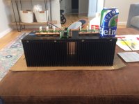
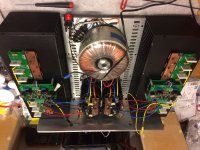
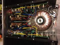
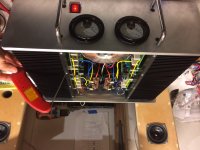
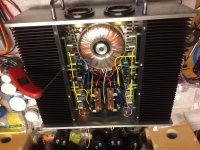
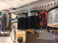
After about 15 years, I have found the time to go back and finish my passively cooled KSA-50 project. I just started testing it last night, slowly bringing up the bias. Running at 37.5v/rail, 3 output pairs/channel, bias currently at 620mv across .68R emitter resistors and stable at 122 degrees F/50 deg C so far, with plans to go to 750mv. The transformer is a 1.2Kw surplus item, with new Kemet 130000uF/63v capacitors being my most expensive parts. The heatsinks were a surplus item I cut in half, I believe a Mersen Fabfin product, and each measure 15.4"Lx5.5"Wx6"H. I had them hard coat anodized for electrical isolation, and mounted all semis directly with just thermal grease for best heat transfer. Chassis top and bottom are .25" plate, front and back are .375" plate. I've mounted some surplus meters for which I still have to add driving circuitry for, but I felt like the front panel needed something.
As you can see, the chassis layout is really tight, as I was trying to keep overall width at 20", means I only had 9" width inside, lol.
Thank you everyone who contributed to this thread and project, it was incredibly rewarding to finally play some music through it!
Enjoy the pictures...beer can for scale.
Attachments
Last edited:


Thank you for the compliments! I'm 99% sure the parts kits I bought were from you, Troy. I also forgot to mention, the boards are pinkmouse 2005, from Mark G. It really was a joy to build these, great design on the boards, Al.
I also forgot to mention that this is one of two stereo amps, I now have everything ready to go to build the second one. I think I originally planned to potentially convert them into KMA monoblocks down the road, with 80v rails. I have been searching for more information on Stuart Easson's ccs front end, but haven't found it yet. Does anyone still have the schematic to his daughter board, or should I try to message him?
My transformers have 0-100-120 primaries, I'm running 0-120 now, but if I run 120vac into the 0-100, it should get me about 45v rails when loaded. Is there any advantage besides higher class AB watts into lower impedances? Not that I need the watts for my setup, just curious.
A more serious question, I'm considering powering the meter circuit with the 100-120 primary taps, autotransformer style, to give me 20 vac. I would flip the inputs and run the 120 tap to N and the 0 tap to L(hot) so that nothing in the low voltage circuit would be more than 20v above ground. I'm sure I only need a few mA. Is there anything wrong with doing this? everything I've read seems to say its ok.
Hi,
Stuart Easson here, I might be able to help with the CCS, but I don't think any of the boards were made by the larger group.
I don't have any boards, I made the prototypes on a bread board and though the results made everything about scaling simpler, for most people it didn't add a whole lot of value.
Let me know what you need.
Stuart
My amp with the PinkMouse boards are still running and are in regular use. This amp is really so easy to build. Was my first ever amp build and it worked on second startup. On first startup I had a cap on the PCB go all puffy because I reversed the polarity. No big deal. Replaced within 5 min with new and worked ever since.
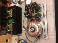
I wonder if some one can help me, as there is no after sales support from the seller. Looking at above pictures can some one kind enough guide me about following
1- Wiring of driver boards to output transistors, is it correct?
2- There is only one ground on driver board, is there any other ground connection?
3- I assume the speaker ground is from filter caps, where is the speaker output?
4- Any modern transistor substitutes for 2SC2240, 2SA970, 2SA968, 2SC2239?
5- I have plenty of MJE15024/25 can I use them or MJE15003/4 is a must?
Hello drmaftoon,
I have recently completed one of these, so I can give you some replies.
However, I do not recognize the board on your image... was it discussed in this thread?
I have read the first two thirds of the thread, and I am familiar with Jan's and Pinkmouse's boards.
Seeing the traces on the bottom side of your boards would help to confirm with certainty.
Do you have the schematic? it would be easy for you to match your board to the schematic discussed in this thread.
1- Wiring of driver boards to output transistors, is it correct?
Yes, it looks correct.
2- There is only one ground on driver board, is there any other ground connection?
Only one ground from the board, this is the same in the boards I know.
Notice that "in -" (minus) is also connected to ground.
3- I assume the speaker ground is from filter caps, where is the speaker output?
Speaker output is any of the connections that say "OUT" on your boards.
4- Any modern transistor substitutes for 2SC2240, 2SA970, 2SA968, 2SC2239?
The substitutes you indicated in your other post are fine.
Other substitutes exist, as long as you respect the relevant ratings;
but then pay attention to the pinout, which may be different (in which case you'd need to bend/swap the pins to put them in the right hole).
5- I have plenty of MJE15024/25 can I use them or MJE15003/4 is a must?[/QUOTE]
You may want to double check:
If you refer to the output transistors, isn't it MJ15003/04 (no "E") ?
these are TO3 metal packages.
I think MJE150xx are TO220, a package for "smaller" power.
If you have MJ15024/25 these are OK for output transistors.
Hope this helps,
This amplifier gives a very nice sound.
Cheers,
pilli
Last edited:
Pilli thank you so much for your prompt help
The seller on AliExpress did not provide me with schematic or BOM.
Here is the link to underside of these boards. They look like "KSA-50 MK2" boards, or at least that is how it was sold to me.
You are right to point out the mistake in output transistor name, there should be no "E".
Best Wishes
The seller on AliExpress did not provide me with schematic or BOM.
Here is the link to underside of these boards. They look like "KSA-50 MK2" boards, or at least that is how it was sold to me.
You are right to point out the mistake in output transistor name, there should be no "E".
Best Wishes
Ok, the bottom side seems to confirm my replies.
(Interesting to see the same TO220 A968/C2238 used for the two stages after the input LTP TO92's; in the "traditional clones" these are TO92 (usually marked Q5, Q6), then TO126 or TO220 usually marked Q7, Q8) - maybe the original Krell used these here.. etc etc.)
You'll find a schematic on the Wiki here on diyaudio
(try this link: KSA50 Clone )
or in the initial pages of this thread.
Minor differences will exist in some component values, don't worry
(but one that is imporatnt is the "compensation" cap: 39pF on your board is the correct value)
_
Hi, may be someone can help me out.
I have manage to get to pinkmouse boards working quite nice. But I'm having a strange problem that i can't figure it out.
As long as i have the input signal and ground shorted my amp stays stable with 250mV bias voltage over 0,47Ohm emmiter resistors. But as soon as I unshort the input signal and connect a dummy load or a speaker my ground starts to drift and i end up with a -72V rail and no middle ground (my posite railt end with ground potencial).
The strange thing is that is happening to both of the boards that I have build.
this is the PS configuration that I'm using
Please much appreciate if some one can help my out
Thanks Octavio
I have manage to get to pinkmouse boards working quite nice. But I'm having a strange problem that i can't figure it out.
As long as i have the input signal and ground shorted my amp stays stable with 250mV bias voltage over 0,47Ohm emmiter resistors. But as soon as I unshort the input signal and connect a dummy load or a speaker my ground starts to drift and i end up with a -72V rail and no middle ground (my posite railt end with ground potencial).
The strange thing is that is happening to both of the boards that I have build.
this is the PS configuration that I'm using
An externally hosted image should be here but it was not working when we last tested it.
Please much appreciate if some one can help my out
Thanks Octavio
- Home
- Amplifiers
- Solid State
- Krell KSA 50 PCB