

Welcome audiodiy community. I’m one of the diy enthusiast, I’ve made some of the simple amplifiers like GainClone but I wanted to try something more complicated. I’m working now on Krell KSA50 and I need your advice.
I’m testing main board (without output transistors) and I have a problem with noise in the speakers. When I connect speaker ground (to the point TRASF on the original schematic) I have noise of the level 70mV on the output. The frequency is from 10Hz to 200kHz on the oscilloscope and it’s change. When I touch an amplifier input (IN+) the frequency is 50Hz with amplitude of 400mV.
When I remove 200R resistor from power supply and I connect speaker to the ground I see on the oscilloscope some noise but it is only 20mV and I do not hear it from speakers.
I’ve checked voltage one the main board and they look OK. I can set up bias from 0V to 2V and it’s stable. Offset I can set up to 1mV and it’s stable.
I’ve connected mainboard to another power supply (another transformer and capacitors) and the problem is the same.
Can you help me and tell what I need to check to resolve it?
hello I just wanted to post the photos of my krell ksa50 ,, I had some problems completing it ...
I bought the pcb on ebay and then I realized a construction defect ... now I have to revise it again.
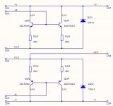
I ask and it happened to someone? the PCBs a diode on the negative polarization side that did not go to the ground?
thank you all
I bought the pcb on ebay and then I realized a construction defect ... now I have to revise it again.
I ask and it happened to someone? the PCBs a diode on the negative polarization side that did not go to the ground?
thank you all
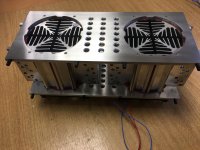
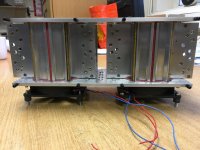
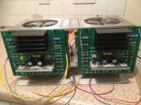
Hi, I have been meaning to build this for years. KSA50 PCB, 4 pairs of output devices per channel, 2 heatsink tunnels and 2 fans. I figured using this configuration I could run the fans slow to minimise noise whilst still keeping everything cool.
Emitter resistors of 0.68 Ohms biased to 330mV gives 60W class A into 8 Ohms, dissipating 160W of heat per channel with 42V rails. Papst 12V fans running at 5V, almost silent and sinks stay approx 20C above ambient. Offset stays within a couple of mV of zero and bias very stable. the plan is to use two separate supplies for the output stage and separate regulated supplies for the PCB, if I ever get that far.
Regards
Alan
Attachments
-
 423908EC-B0CE-4FCA-895E-D0F63C415D19.jpg981 KB · Views: 856
 -
 1D4F279C-592A-43FC-A79D-090F215C42BD.jpg865.5 KB · Views: 824
 -
 73930D04-B9B6-4019-BA7C-3F1B36AB121D.jpg839 KB · Views: 807
 -
 0FCB4246-B93E-45B9-842D-09898C6066EA.jpg955.3 KB · Views: 779
 -
 5B58CDD0-02FF-4426-A7FB-B91C00E241EB.jpg775.9 KB · Views: 753
 -
 280759D4-8550-440F-B74C-AC76E4495A8A.jpg880.7 KB · Views: 406
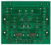
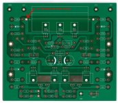
my krill ksa50 clone 1:1
hello everyone this and my krell ksa50
works on 35v tracks, 400m bias current the transistors reach 50/60 degrees and is a beautiful sound.
used components;
ksa992 ksc1845
2sa968 2sc2238
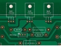
mje15030 / 31
MJ15003 / 4
you can see and listen on my "gibronzo" youtube channel thanks/Users/Giovanni/Desktop/IMG_7089.jpg/Users/Giovanni/Desktop/foto krell 2.jpg/Users/Giovanni/Desktop/15568ECB-6ADF-4350-91F1-EEC4492887A4.jpg/Users/Giovanni/Desktop/foto krell.jpg
hello everyone this and my krell ksa50
works on 35v tracks, 400m bias current the transistors reach 50/60 degrees and is a beautiful sound.
used components;
ksa992 ksc1845
2sa968 2sc2238
mje15030 / 31
MJ15003 / 4
you can see and listen on my "gibronzo" youtube channel thanks/Users/Giovanni/Desktop/IMG_7089.jpg/Users/Giovanni/Desktop/foto krell 2.jpg/Users/Giovanni/Desktop/15568ECB-6ADF-4350-91F1-EEC4492887A4.jpg/Users/Giovanni/Desktop/foto krell.jpg
I've had the Pinkmouse boards for a few years now, 95% completed. Life and other stuff has conspired to delay my project. Recently I've come across replica pcbs. The Pinkmouse boards are much smaller.


Now I need to decide to use the new boards or not to rebuild my real KSA50 (I have an original Krell KSA50 case, transformers and heatsink tunnel)
Now I need to decide to use the new boards or not to rebuild my real KSA50 (I have an original Krell KSA50 case, transformers and heatsink tunnel)
Hi, I have been meaning to build this for years. KSA50 PCB, 4 pairs of output devices per channel, 2 heatsink tunnels and 2 fans. I figured using this configuration I could run the fans slow to minimise noise whilst still keeping everything cool.
Emitter resistors of 0.68 Ohms biased to 330mV gives 60W class A into 8 Ohms, dissipating 160W of heat per channel with 42V rails. Papst 12V fans running at 5V, almost silent and sinks stay approx 20C above ambient. Offset stays within a couple of mV of zero and bias very stable. the plan is to use two separate supplies for the output stage and separate regulated supplies for the PCB, if I ever get that far.
Regards
Alan
Hi Alan,
I've just recieved the same KSA 50 boards that you have built; looks really good btw.
Could you tell me what heatsinks on the PCB you used for your build please? The ones for the VAS and LTP.
Ta.
That has been discussed here a while ago. Solution and explanation are in post #9126, but go several pages back and read carefully these previous posts leading to conclusion.hello I just wanted to post the photos of my krell ksa50 ,, I had some problems completing it ...
I bought the pcb on ebay and then I realized a construction defect ... now I have to revise it again.
I ask and it happened to someone? the PCBs a diode on the negative polarization side that did not go to the ground?
thank you all
Simply, one side of the diode is connected to nowhere. You have to connect that side properly, according to the scheme.
i migliori saluti

Last edited:


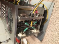
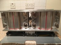
I also have the original Avel Lindberg trafos and part of the original wiring loom.
The heatsink tower, thermal cut-out and fan is from Krell, you can also see some of the transistors are original Krell.
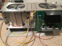
The green PCB is a clone PCB from China, it looks very well made and it is a 1:1 reproduction, the holes line up nicely.
Three of the photos show the 1:1 clone and Pinkmouse pcb.
You can see the heatsink I'll be using for the driver board, I'll be cutting it up into 4 heatsinks and two for the pre-driver.
- Home
- Amplifiers
- Solid State
- Krell KSA 50 PCB