And when I hear significant differences between resistor manufacutrer /types in the I/V position of my DAC thanthese are as well oscillations ? No, Sir. Interesting hypothesis, but wrong. It all depends which device you use. And the 6922 was famous for its tendencies to oscillate, but if you use a tube which has not this weakness (in my case 801A) you actually can have much nicer music by not have a grid stopper at all. It all depends on the amplifying device.
...so back to the KSA50: I believe there are different input tranistor choices...so if there is a types which does not really need a gridstopper...would be a big plus.
By the way: Did any one care to play around with different PSU-Setups ? I understand that Krell put in 47000uf after the bridge, right ?
I will go with
- Hexfreds
- CLC with some Hammond chokes
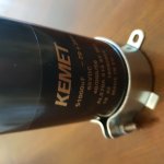
- Now, the C...just Big and bad ? Has anyone compared Brands/Types ? I can definetely hear a difference between Silmic and Epcos (warm and lush vs. bright and stiff) ? Just found those cheap:
https://content.kemet.com/datasheets/KEM_A4034_PEH200.pdf ... 7milliohm ESR at 47000/100V...lifetime 19000hours for voltage and current...what do you think ?
...so back to the KSA50: I believe there are different input tranistor choices...so if there is a types which does not really need a gridstopper...would be a big plus.
By the way: Did any one care to play around with different PSU-Setups ? I understand that Krell put in 47000uf after the bridge, right ?
I will go with
- Hexfreds
- CLC with some Hammond chokes
- Now, the C...just Big and bad ? Has anyone compared Brands/Types ? I can definetely hear a difference between Silmic and Epcos (warm and lush vs. bright and stiff) ? Just found those cheap:
https://content.kemet.com/datasheets/KEM_A4034_PEH200.pdf ... 7milliohm ESR at 47000/100V...lifetime 19000hours for voltage and current...what do you think ?
Last edited:
ALS70A513KF063 KEMET | Mouser Norway
I will be using these, mainly due to price. Paired with KBPC bridge.
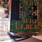
Silmic has different spacing than green boards im using(KSA50mk2). Im using Silmic for feedback, Silver mica for pF, 2SA968/2238(pulled parts) and KSA992/KSC1845. MJL4302/MJL4281 for output with 0R68 emitter. Have made PCB for output with zobel.
Will be using UPC1237 protection boards. It did save my speakers in another(oscillating) project.
I will be using these, mainly due to price. Paired with KBPC bridge.
Silmic has different spacing than green boards im using(KSA50mk2). Im using Silmic for feedback, Silver mica for pF, 2SA968/2238(pulled parts) and KSA992/KSC1845. MJL4302/MJL4281 for output with 0R68 emitter. Have made PCB for output with zobel.
Will be using UPC1237 protection boards. It did save my speakers in another(oscillating) project.
The design of the amplifier determines a idling current "sweet spot", which means that at a certain amount of idling current, amplifier has the best sound and lowest, or satisfactory, amount of harmonic distortion. So basically, high bias is not a guarantee for excellent result...optimal bias is what you need. You can, of course, go either way, high bias/lower rail voltage or lower bias/higher rail voltage as long as power dissipation is within the limits allowed by output devices and cooling ability.
Neychi, may I ask for advise what the sweet spot is regarding current per device / rail ?
If I plug in some numbers, I would get at the above 250mA/0,5r only 27W class A if the spreadsheet is right:
Inputs
Number of output devices: 3 Pairs
Voltage rails (per rail): 42 volts
Emitter resistance (per device): 0,5 ohms
Bias voltage per Emmiter resistor: 250 mv
Idle bias per device 500,0 mA
Speaker ohms 6 ohms
Results
Idle bias per device: 0,500 Amps
Total Amplifier bias (per rail)** 1,50 Amps
Total Amplifier bias (both rails) 3,00 Amps
Total Dissipation (per channel) 126,0 Watts
Dissipation per device pair at idle 21,0 watts
Class-A output: Peak 54,0 Watts peak
Class-A output: RMS 27,0 Watts RMS
Efficiency 21,43 %
Max Class-AB RMS (1 kVA Toroid p/CH 5% reg) 117,59 Watts RMS
Max Class-AB factor (100%=ideal load, Krell/565's = 91%, 555=70% regulation of rails at max power) 80 %
** A.K.A total bias.
ALS70A513KF063 KEMET | Mouser Norway
I will be using these, mainly due to price. Paired with KBPC bridge.
Silmic has different spacing than green boards im using(KSA50mk2). Im using Silmic for feedback, Silver mica for pF, 2SA968/2238(pulled parts) and KSA992/KSC1845. MJL4302/MJL4281 for output with 0R68 emitter. Have made PCB for output with zobel.
Will be using UPC1237 protection boards. It did save my speakers in another(oscillating) project.
I simulated the PSU in PSUD2 (30VAC, 1.5 per rail)...current ripple around 13A...but voltage ripple is 300mV with a plain 47000uF filter...300mV is not a dream...
Now, lets look at LCL: your current rating of the 24000uF/63V...it is at 13.2A, so maybe good enough...24000uF-1,5mH-24000uF brings your voltage ripple down to 30mV !!
If you want to optimize a little the transient response / resonance you start maybe with a smaller 13000uF/100V (rated at 14.2A) and let a bigger 33000uF follow. When you do this with a Hammond 159ZJ 10mH in between, we are now down to 6mV !!! And at a nearly perfect impulse behavior (R=0,4ohm in between Caps).
Energy storage capacity is the same or better, costs are only marginla higher...so why is not everybody using this path...
Neychi, may I ask for advise what the sweet spot is regarding current per device / rail ?
If I plug in some numbers, I would get at the above 250mA/0,5r only 27W class A if the spreadsheet is right:
Inputs
Number of output devices: 3 Pairs
Voltage rails (per rail): 42 volts
Emitter resistance (per device): 0,5 ohms
Bias voltage per Emmiter resistor: 250 mv
Idle bias per device 500,0 mA
Speaker ohms 6 ohms
Results
Idle bias per device: 0,500 Amps
Total Amplifier bias (per rail)** 1,50 Amps
Total Amplifier bias (both rails) 3,00 Amps
Total Dissipation (per channel) 126,0 Watts
Dissipation per device pair at idle 21,0 watts
Class-A output: Peak 54,0 Watts peak
Class-A output: RMS 27,0 Watts RMS
Efficiency 21,43 %
Max Class-AB RMS (1 kVA Toroid p/CH 5% reg) 117,59 Watts RMS
Max Class-AB factor (100%=ideal load, Krell/565's = 91%, 555=70% regulation of rails at max power) 80 %
** A.K.A total bias.
I am running 3 output pairs per side with Re = 0R5, and my bias is 1.92A (640mA per device), which I think is just about as much as I will get out of my setup. I have decent sized heatsinks. My pics are somewhere in this thread. My voltage per rail is 39V. I have basic C PSU with no R or L. The KSA50 circuit has decent PSRR, which is why is did not bother with R or L filtering. Big 47mF caps.
Last edited:
In that case go for the higher voltage version, Dave. After all, you listened to it and you liked it")
Hi neychi just an idea at moment but would I gain anything by adding another MJ21194G / MJ21193G T03 plus 0.5 ohm resistor per channel so I would have 3 pairs per channel with 48v rails.
Would this give me more class A power at 48v with the same bias as 2 pair kind of in between ksa 50 and ksa 100.
my transformers will be 750VA 34.5 or 750VA 37.5v.
Neychi, may I ask for advise what the sweet spot is regarding current per device / rail ?
If I plug in some numbers, I would get at the above 250mA/0,5r only 27W class A if the spreadsheet is right:
Inputs
Number of output devices: 3 Pairs
Voltage rails (per rail): 42 volts
Emitter resistance (per device): 0,5 ohms
Bias voltage per Emmiter resistor: 250 mv
Idle bias per device 500,0 mA
Speaker ohms 6 ohms
Results
Idle bias per device: 0,500 Amps
Total Amplifier bias (per rail)** 1,50 Amps
Total Amplifier bias (both rails) 3,00 Amps
Total Dissipation (per channel) 126,0 Watts
Dissipation per device pair at idle 21,0 watts
Class-A output: Peak 54,0 Watts peak
Class-A output: RMS 27,0 Watts RMS
Efficiency 21,43 %
Max Class-AB RMS (1 kVA Toroid p/CH 5% reg) 117,59 Watts RMS
Max Class-AB factor (100%=ideal load, Krell/565's = 91%, 555=70% regulation of rails at max power) 80 %
** A.K.A total bias.
Basically, what we want is that the transistor works in a linear area. Linear area starts at some amount of quiescent current for a particular transistor (see I-V curves in the datasheet). Many people here see the solution in pushing the transistor deep into class A to provide the linear area at lower impedances. This is fine, however, it leads to a number of other problems such as large thermal load of the transistor, large dissipation, etc. When setting the quiescent current , you'll find that at certain amount of current there is no change in the sound quality, so there is no point in increasing the current much further. In your case, I think 27 W of class A is more than enough for normal listening.
Hi neychi just an idea at moment but would I gain anything by adding another MJ21194G / MJ21193G T03 plus 0.5 ohm resistor per channel so I would have 3 pairs per channel with 48v rails.
Would this give me more class A power at 48v with the same bias as 2 pair kind of in between ksa 50 and ksa 100.
my transformers will be 750VA 34.5 or 750VA 37.5v.
This would increase the total quiescent current...so yes, the power in Class A would be higher but the dissipation and the heating would increase too. You'll need large heatsinks or sufficient fan cooling. Two 750VA transformers will be more than enough.
Basically, what we want is that the transistor works in a linear area. Linear area starts at some amount of quiescent current for a particular transistor (see I-V curves in the datasheet). Many people here see the solution in pushing the transistor deep into class A to provide the linear area at lower impedances. This is fine, however, it leads to a number of other problems such as large thermal load of the transistor, large dissipation, etc. When setting the quiescent current , you'll find that at certain amount of current there is no change in the sound quality, so there is no point in increasing the current much further. In your case, I think 27 W of class A is more than enough for normal listening.
This would increase the total quiescent current...so yes, the power in Class A would be higher but the dissipation and the heating would increase too. You'll need large heatsinks or sufficient fan cooling. Two 750VA transformers will be more than enough.
Hi I was just wondering would 2 x 500VA transformers be large enough for my amps 3 x MJ21194G and 3 x MJ21194G per channel.
I have added an extra MJ21194 /93 as my heat sinks are quite large and double fan cooled in push pull.
750VA transformers are a bit of a tight fit.
Also I have contacted the transformer supplier and he has told me that 230v/36v transformers actually gives out 37.5v x 1.41 = 52.3v on my UK voltage as my mains supply is 240V at sockets.
He does a 33v version which I am guessing will give me about 34v x 1.41 =48v on 240v at sockets.
I have read expect to loose 2v or more after rectification and load so would 37.5v be a bit high or 34v be a better option.
sorry to be a pain as i am no good at the maths side of electronics.
Hi Dave,
Which boards will you use, red or green? If you'll use red ones, your transformers will be just fine. Red boards are used for ksa50mk2 and ksa100mk2 (same circuit) so a little higher voltage should not be a problem, just use a higher wattage zeners (3W).
Btw., if you are planning to add a clc or crc filter to the power supply it will additionally cause a rail voltage drop.
500VA transformers will also be good.
Hi Neychi thank you for your help as you can probably see this is my first amp build.
By boards are green ksa 50 mk2 with zener 3w 27v diodes.
My power supply is just 2 capacitors like original krell but with added 0.1uf capacitors on each cap for extra filtering plus I was going to add some kind of bleed resistor to each cap.
Thanks neychi
All of my components are from mouser electronics or RS components except the 2SA970 and 2SC2240 mouser and RS did not have these so I got them from a company called cricklewood electronics.
The only components I got from ebay was my soft start pcbs and speaker protection pcbs.
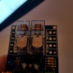
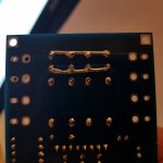
I did not trust the omron relays on the speaker protection pcbs so I changed them to bigger 16A omron relays from RS components.
I have bridged relays to run as mono pcb speaker protection instead of stereo.
All of my components are from mouser electronics or RS components except the 2SA970 and 2SC2240 mouser and RS did not have these so I got them from a company called cricklewood electronics.
The only components I got from ebay was my soft start pcbs and speaker protection pcbs.
I did not trust the omron relays on the speaker protection pcbs so I changed them to bigger 16A omron relays from RS components.
I have bridged relays to run as mono pcb speaker protection instead of stereo.
Attachments
Thanks neychi
All of my components are from mouser electronics or RS components except the 2SA970 and 2SC2240 mouser and RS did not have these so I got them from a company called cricklewood electronics.
The only components I got from ebay was my soft start pcbs and speaker protection pcbs.
I did not trust the omron relays on the speaker protection pcbs so I changed them to bigger 16A omron relays from RS components.
I have bridged relays to run as mono pcb speaker protection instead of stereo.
I forgot for a minute mills 0.5R resistors 0.1uf Jantzen audio caps and mica caps are from HIFI collective.
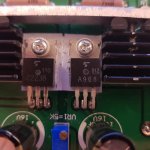
I'm afraid I do not have good news for you. These are definitely not original Toshiba transistors, but some generic Chinese type. Identical are selling on ebay. Today it is almost impossible to find new, original Toshibas. It would be better to try to find replacement transistors like Sanyo 2sa1011 / 2sc2344 or Toshiba 2sa1837 / 2sc4793.
I'm afraid I do not have good news for you. These are definitely not original Toshiba transistors, but some generic Chinese type. Identical are selling on ebay. Today it is almost impossible to find new, original Toshibas. It would be better to try to find replacement transistors like Sanyo 2sa1011 / 2sc2344 or Toshiba 2sa1837 / 2sc4793.
Thank you Neychi I will change them.
It looks like mouser and RS components do not list them so it must be those I got from cricklewood electronics because no components come from ebay for that reason.
I will check for Sanyo or toshiba.
Is Sanyo or Toshiba best or does it not matter.
Thanks neychi
All of my components are from mouser electronics or RS components except the 2SA970 and 2SC2240 mouser and RS did not have these so I got them from a company called cricklewood electronics.
The only components I got from ebay was my soft start pcbs and speaker protection pcbs.
I did not trust the omron relays on the speaker protection pcbs so I changed them to bigger 16A omron relays from RS components.
I have bridged relays to run as mono pcb speaker protection instead of stereo.
This is a good idea Dave.
-Dan
change them
Originals : https://www.diyaudio.com/forums/swap-meet/328924-fs-various-semiconductors-opamps.html#post5578145
(compare the SOA of A1011/C2344, A1837/C4793, A968/C2238)
- Home
- Amplifiers
- Solid State
- Krell KSA 50 PCB