Yes, if Nelson Pass's F5 amplifier in post #47 is operating in the small-signal, non-slewing regime, then its actual slew rate will be even greater than 22 volts/usec.
BTW here is a conventional 3-stage amplifier (LTP -> VAS -> OPS) I built earlier this year, operating in slew rate limiting (500 kHz square wave input, clipped output). Slope is about 120 volts per microsecond. A relatively large number of components were lavished upon the "clip cleanly and exit clipping rapidly" portion of the design.
_
Attachments
Last edited:
They are two different things.@jcx,
Which isn´t wrong as the rate of change of a signal is that, but for an amplifier the slew rate is usually a feature of the device but not signal dependent, as it is in fact the maximum rate of change possible to get at the output of the device.
@PMA,
That´s why i provided both possible cases.
At that point we were talking about "rise time" not slew rate. You mentioned the _unit_ step function and the "unit" part is the reason why it is not amplitude dependent, as the unit step is just one unit.
But "rise time" is usually defined as the time span needed to rise from 10% signal level to 90% signal level and i think that illustrates why it depends on the amplitude. (And likewise the "fall time" as the time span needed to come down from 90% signal level to 10%)
As said above, the "slew rate" is a feature of the amplifier/device and is a typical large signal parameter.
Your example below illustrates that, the amplifier obviously isn´t slewing the whole time but at a portion of the uprising part.
In the posts where most people were talking about real music driven signals, they slew rate is, obviously (as dV/dt is), related to amplitude.
The slew rate of an amplifier does not depend on a signal, but it is instead measured as the rise time (RT) to a given V (SlewRate=V/RT), when an impulse is applied to its inputs.
I think you are talking about analogue sources rather than CD. With CD the filtering will approximately kill anything above 20KHz so there will be no voltage slopes above, say, 6V/us for a 40V amplitude...ever. Do you agree?Of course we can quibble, but several of us did and published the research approximately 40 years ago, and the measurements still show that a 10us rise-time waveform should be passed cleanly with hi fi rated audio equipment. For example, my 30ips analog recorder has a 10us rise-time, as does a TIM-30 test signal in my SR-1 (the easier TIM test).
If you can't pass a 10us rise-time waveform, then you could have some TIM, the same goes if you ever play a vinyl record with an MC cartridge.
For a non-CD source the jury is out. So I think you are simply arguing for a much higher slew rate capability for amplifiers to accommodate using sources that don't brick wall above 20kHz. Is that right? Particularly high NFB circuits where the feedback will cause saturation problems when the output is slew limited.
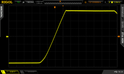
Yes, if Nelson Pass's F5 amplifier in post #47 is operating in the small-signal, non-slewing regime, then its actual slew rate will be even greater than 22 volts/usec.
BTW here is a conventional 3-stage amplifier (LTP -> VAS -> OPS) I built earlier this year, operating in slew rate limiting (500 kHz square wave input, clipped output). Slope is about 120 volts per microsecond. A relatively large number of components were lavished upon the "clip cleanly and exit clipping rapidly" portion of the design.
_
Seems like your lavishing was well apportioned though! Overprovisioned front end rails with a modified baker clamp?
Have a look at Vzaichenko's designs. Especially his Lichtstark amplifier shows clear effort, but tremendous slew rate.
Best regards!
I've got an older one - even "faster" one
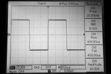
The picture attached shows it makes 20Vpp step in 400nS (or so - the scope's measurement system rounds it to the nearest 20). R load = 8 ohm.
It makes the same 400nS at 100Vpp, meaning the slew rate is around 250V/uS. 20KHz square wave looks better that some other amplifiers' 1KHz square wave
CFA front-end, Hex-FET based OPS. Not the lowest distortion level, but very good profile.
I agree - this kind of slew rate is somewhat an overkill for audio, nevertheless this one demonstrates extremely natural sound - the main amplifier in my home system since the end of 2015.
If somebody's interested, a brief project description is here: CF-FET V2.0
It's not that difficult to make a high-slew-rate amplifier with the right engineering solutions - voltage amplification stages topology, feedback arrangement, etc.
Cheers,
Valery
Attachments
It's not that difficult to make a high-slew-rate amplifier with the right engineering solutions - voltage amplification stages topology, feedback arrangement, etc.
Cheers,
Valery

Cleanly reproduce the 9th or 11th harmonic of 20 kHz might be a goal
Show me content that has those frequencies.
Relatively high slew rate is fairly easy to achieve these days that meet the TIM-30 measurement criterion that we put forth more than 40 years ago. I don't even bother to test for TIM in any of my designs these days, because I know that there isn't any, but then 100V/us is typical of any of my power amps. I don't find more necessary either, although I have made faster amps.
Rationalizing that 10V/us or so is enough for a power amp is just asking for compromised performance.
Rationalizing that 10V/us or so is enough for a power amp is just asking for compromised performance.
Relatively high slew rate is fairly easy to achieve these days that meet the TIM-30 measurement criterion that we put forth more than 40 years ago. I don't even bother to test for TIM in any of my designs these days, because I know that there isn't any, but then 100V/us is typical of any of my power amps. I don't find more necessary either, although I have made faster amps.
Rationalizing that 10V/us or so is enough for a power amp is just asking for compromised performance.
Agree.
For me, more important to have low enough THD at 20kHz than to make high slew rate, as Bob Cordell's suggestion in his book. But, likely we can not make low enough THD at 20kHz if we have low slew rate.
@PMA,
No need to step aside, as you´re right (that´s what the tau gives us ), and sorry for the misundersting on my side.
I only took exception as we know that the rise time (wrt to amplifiers) depends on variables like the amplitude and the actual phase reserve with the load involved. If an amplifier is near oscillation the square wave will show ringing, but (given the 10% to 90% definition) the rise time will be shorter than for the overdamped condition.
But i think, we (and Mark Johnson) have settled it already and again sorry for the hassle.
@Hotice,
I think there at the core no big differences, as
-) the slew rate is a property of the amplifier
-) that is not signal dependent (provided that the signal evokes slewing)
-) it might be load dependent
A difference i think exists in the definitions, as
-) slew rate is a large signal parameter
while
-) rise time is a small signal parameter measured under the condition that the amplifier is _not_ slewing
I mentioned that the rise time (of the step response rising edge) does not depend on amplitude for a linear circuit like RC low pass filter. Of course not speaking about non-linear circuit like an amplifier.
And it is a fact! For RC low pass, Vout = Vo*(1 - exp(t/RC)), Vo amplitude of the step.
Tr(10% - 90%) does not depend on amplitude of the input step! Always Tr = 2.2*RC, you may calculate it, just use the equation above.
Maybe we have some kind of misunderstanding, but I am not going to step aside this fact.
No need to step aside, as you´re right (that´s what the tau gives us
), and sorry for the misundersting on my side. I only took exception as we know that the rise time (wrt to amplifiers) depends on variables like the amplitude and the actual phase reserve with the load involved. If an amplifier is near oscillation the square wave will show ringing, but (given the 10% to 90% definition) the rise time will be shorter than for the overdamped condition.
But i think, we (and Mark Johnson) have settled it already and again sorry for the hassle.
@Hotice,
They are two different things.
In the posts where most people were talking about real music driven signals, they slew rate is, obviously (as dV/dt is), related to amplitude.
The slew rate of an amplifier does not depend on a signal, but it is instead measured as the rise time (RT) to a given V (SlewRate=V/RT), when an impulse is applied to its inputs.
I think there at the core no big differences, as
-) the slew rate is a property of the amplifier
-) that is not signal dependent (provided that the signal evokes slewing)
-) it might be load dependent
A difference i think exists in the definitions, as
-) slew rate is a large signal parameter
while
-) rise time is a small signal parameter measured under the condition that the amplifier is _not_ slewing
I only took exception as we know that the rise time (wrt to amplifiers) depends on variables like the amplitude and the actual phase reserve with the load involved. If an amplifier is near oscillation the square wave will show ringing, but (given the 10% to 90% definition) the rise time will be shorter than for the overdamped condition.
But i think, we (and Mark Johnson) have settled it already and again sorry for the hassle.
We are in perfect agreement on this and I apologize I did not read more patiently.
In my experience of designing power amplifiers, it is important to understand why specs are what they are and to question them. If you don't know why you need such and such a slew rate then you are fumbling in the dark. I am also numb to authorities who decree acceptable specs as I have seen too many instances where that declaration was either wrong or mis-informed or dishonest. You might think papers published in journals are trustworthy but even these sometimes contain bad logic or bad math or both.
I think this is what this thread is about - understanding what slew rate is actually acceptable and why. Not just who can measure the highest slew rate. The first place to start is not with the amplifier itself but with the source material. The source defines what slew rate the amplifier is required to provide. With CD this isn't very high.
The next question is what topology, circuit and load considerations affect an amplifiers ability to provide this slew rate with acceptable distortion. It might be that a set of solutions happens to also provide excessively generous slew rate or it may be some solutions have just enough slew rate. Both are acceptable. This question is no loner to do with what is acceptable for the output but concerns circuit choices that affect other things like distortion. You may blow past the slew rate target but end up with a mediocre sounding circuit.
In my experience it is not helpful to set goals way beyond what is needed because this can often impose undesirable trade-offs in other areas. Anyone can declare that 100V/us is an acceptable slew rate but this is not helpful. Doggedly aiming for this could well constrain opportunities in other areas that would have led to better sound quality. The same principle applies to aiming for excessively low output impedance and wide bandwidth and huge loop gain and so on.
I suggest a discussion of source based slew rate requirements.
Last edited:
traderbam said:I suggest a discussion of source based slew rate requirements.
Great, this is right on line with my original post questionnings.
I have learned a lot from all answers.
The most important being the usefulness of the slew rate as published in datasheet and amp measurements.
Indeed it is a non linear parameter, so doesn't apply to the linear behavior we look for in an audio amplifier. So, the use of that slew rate is higly questionable, misleading, if not plain wrong.
Here are results from a LTSpice simulation on a LT6090 high voltage op amp.
My ( very simple ) test jig is +-50v rails, Rload 10k, Gain Av= +3 ( done with 1k,2k nfb ).
I look at the THD at 20KHz, 40Khz, 80Khz. AND for each frequency I try various sine signal levels.
At low levels I have good THD, when I increase the level, at some level ( much before clipping ), THD increases very bad sharply.
Raw results:
20Khz Vout 30v peak thd 0.0007%, 36v thd 0.07% 37.5v thd 0.65%
40Khz Vout 12v peak thd 0.001%, 17.5v thd 0.007, 18v thd 0.13%
80Khz Vout 8.55v peak thd 0.008%, 9v thd 0.35%
Summary: THD becomes bad at
Vout= 36v peak @20Khz
Vout =18v peak @40Khz
Vout = 9v peak @ 80Khz
Because of this Amplitude/frequency dependancy, it clearly hints for a slew rate limitation. Using dV/dt max for a sine wave = Vpeak x 2Pi x Frequency,
the conclusion is: THD becomes bad at dV/dt > 4.5V/uS
This means the "clean slew rate" the LT6090 ( the dv/dt it is able to give in its linear behavior ) is 4.5 V/uS.
On the other hand the datasheet gives
SR = 21V/uS typ for LT6090
SR = 37V/uS typ for LT6090-5
LTSpice simulation on my test jig gives about 30V/uS which is fair enough to me.
This shows that SR and dV/dt max for a clean amplification are diferent beats.
SR = 30V/uS versus dV/dt 4.5V/uS
Last edited:
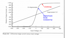
Yes, slew-rate limiting occurs when the input differential pair steers >99% of the tail current into one leg, and <1% of the tail current into the other leg. But departure-from-linearity occurs sooner than that. This figure from Bob Cordell's textbook illustrates the phenomenon.
_
_
Attachments
You can rephrase the question
If, for example, you decide you want to be no more than 15% away from perfect balance, then you want slew limiting at (20 kHz / 0.15) = 133 kHz. "133 kHz full power bandwidth." Which is a slew rate of 0.83 volts per microsecond per volt of supply.
"How high do I want my amplifier's slew rate to be?"
so that it becomes"How far from perfect balance (50%/50% current in the LTP input stage) do I want my amplifier to operate, when reproducing a maximum amplitude 20 kHz sinewave?"
If, for example, you decide you want to be no more than 15% away from perfect balance, then you want slew limiting at (20 kHz / 0.15) = 133 kHz. "133 kHz full power bandwidth." Which is a slew rate of 0.83 volts per microsecond per volt of supply.
I am trying to point out the fact that very high slew rate does not automatically mean low 20kHz distortion at higher amplitudes. Sufficient slew rate is only a necessary, but not satisfactory condition. Usually slew rate 5x higher than the dv/dt corresponding to maximum 20kHz output amplitude is more than enough. Even 1kV/us does not indicate to low HF distortion. The output stage may be pretty non-linear at HF although the slew rate is high. For 200W/8ohm amplifier, maximum dv/dt of 20kHz output full swing is 7.1V/us and slew rate of 40-50V/us would be more than enough. No need to go 500V/us, just troubles.
From simulations of the LT6090, it has SR = 30V/uS....BUT, is only able to output dV/dt = 4.5V/uS.
With this figure ( That has the same unit as a Slew Rate ) which is not the Slew Rate but the dV/dt the op amp is able at the output.
Can one consider the LT6090 is a good amp as a front end for a 100W rms in 8 ohm amplifier.
This figure means, the amplifier would have low THD for up to
36Vpeak @ 20Khz ( 81Watt rms )
18Vp @ 40 khz (20W )
9Vp @20Khz ( 5W )
Is there such high levels beyond 20Khz in real audio ?
Good microphones are flat -3dB up to 40Khz.
No ear drum or tweeter could stand such hight levels.
Last edited:
Is there such high levels beyond 20Khz in real audio ?
No. It is all about margin you want to have.
- Status
- This old topic is closed. If you want to reopen this topic, contact a moderator using the "Report Post" button.
- Home
- Amplifiers
- Solid State
- Slew Rate