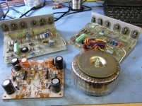
I just couldn't resist rescuing this assembled Maplin 50W amplifier kit on eBay, harking back to the good old days when Maplins were educational and before they started to sell crate-loads of Chinese junk . The seller had stripped the boards and transformer out of a poorly-built amplifier chassis and looking at the boards, you can probably understand why. I don't think the original constructor had too much idea and the amplifier boards are assembled badly with a mish-mash of different components e.g carbon, carbon film and metal film, vintage 1978 capacitors and flying-lead transistors. Clearly, his electronics scrap box was raided as the component source. The pre-amp board is not too bad and can be used as is but I will completely strip down the amplifier boards and start again with new components, taking the opportunity to use lower noise transistors and improve the capacitor decoupling. I have all the other components required already so lets hope I can get this amplifier up and running soon before I get too teary-eyed with nostalgia
. The seller had stripped the boards and transformer out of a poorly-built amplifier chassis and looking at the boards, you can probably understand why. I don't think the original constructor had too much idea and the amplifier boards are assembled badly with a mish-mash of different components e.g carbon, carbon film and metal film, vintage 1978 capacitors and flying-lead transistors. Clearly, his electronics scrap box was raided as the component source. The pre-amp board is not too bad and can be used as is but I will completely strip down the amplifier boards and start again with new components, taking the opportunity to use lower noise transistors and improve the capacitor decoupling. I have all the other components required already so lets hope I can get this amplifier up and running soon before I get too teary-eyed with nostalgiaAttachments
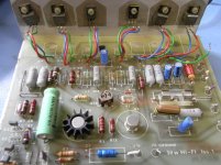
Horrible little amplifier!
The schematics are available here https://www.scribd.com/doc/38418078/50W-HiFi-Power-Amplifier-LW35Q-Maplin-Kit
Have fun.
The schematics are available here https://www.scribd.com/doc/38418078/50W-HiFi-Power-Amplifier-LW35Q-Maplin-Kit
Have fun.
Can someone tell me/us how to run the three wires to the remote power devices?
a.) Twist all three?
b.) Twist Collector and Emitter and keep Base separate, but close, c.) base farther away?
d.) Run all three parallel with no gaps and base on the inside, or e.) Collector on the inside or f.) Emitter on the inside?
g.) Keep all three parallel but separated by 3mm again which (h & i) on the inside?
j.) Other options?
The reason why it was known as 'horrible' was down to the power transistor fixings coming loose. Just a poor finish but as you say, quite advanced for the 80s.Not sure horrible is the right word tbh. It was quite an advanced (for diy) design back in the day.
All three twisted is probably ok in most power devices. The capacitative coupling of the B to C would be small in relation to the intrinsic capacitance of the device and the current loop would be the smallest.Can someone tell me/us how to run the three wires to the remote power devices?
It always seemed to be whatever was easiest to manufacture.
Actually I have a System/360 power supply sitting outside under a garbage bag and the main currents run on a busbar and the heatsink; the base is just a fly wire. I had thoughts to upcycle it to a mono amplifier but never got to it. It wouldn't be hard if the devices on the control card are still in working condition as the diff amp is already there.
Actually I have a System/360 power supply sitting outside under a garbage bag and the main currents run on a busbar and the heatsink; the base is just a fly wire. I had thoughts to upcycle it to a mono amplifier but never got to it. It wouldn't be hard if the devices on the control card are still in working condition as the diff amp is already there.
Ugh, connecting those transistors with wires like that has probably caused a load of problems... not to mention that Q6 is not in contact with the heatsink at all, so the amplifier was probably going into thermal runaway.
The correct output transistors are BD711/BD712 which are now obsolete, but you can still get them if you look around. Failing that, it looks like D44H11/D45H11 from OnSemi should work very well.
I'd definitely build some sort of DC fault protection kit as well though!
The correct output transistors are BD711/BD712 which are now obsolete, but you can still get them if you look around. Failing that, it looks like D44H11/D45H11 from OnSemi should work very well.
I'd definitely build some sort of DC fault protection kit as well though!
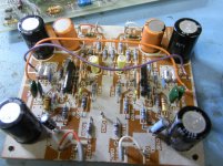
I don't think the boards were ever powered up and the components are definitely vintage and obsolete. The flying-lead transistor madness was probably because the constructor didn't have skills to mount the pcb and output stage transistors onto the heatsink, as per the designers intention. Speaker protection circuit definitely a good idea. At least I can test the re-built boards on the bench first with 8 ohm test load, to check performance and stability.
"...flying-lead transistor madness"
Was it madness? Have you ever seen the arrangement Quad used in the 33 power amplifier (circa 1968?)? 2N3055s mounted about 10 - 14 inches from the PA boards, and connected over that distance with surprisingly thin flex. Didn't cause problems. Fact is that those earlier 2N3055s had a much lower frequency response than later versions - probably only thing that prevented it turning into a 50W oscillator.
Was it madness? Have you ever seen the arrangement Quad used in the 33 power amplifier (circa 1968?)? 2N3055s mounted about 10 - 14 inches from the PA boards, and connected over that distance with surprisingly thin flex. Didn't cause problems. Fact is that those earlier 2N3055s had a much lower frequency response than later versions - probably only thing that prevented it turning into a 50W oscillator.
"...flying-lead transistor madness"
Was it madness? Have you ever seen the arrangement Quad used in the 33 power amplifier (circa 1968?)? 2N3055s mounted about 10 - 14 inches from the PA boards, and connected over that distance with surprisingly thin flex. Didn't cause problems. Fact is that those earlier 2N3055s had a much lower frequency response than later versions - probably only thing that prevented it turning into a 50W oscillator.
+1
Do the math and it's nH of inductance, pF's stray capacitance and possible transformer-action from mutual inductance in flying-lead power transistor wiring.
It looks sloppy and bad but I haven't seen it cause problems with old fT a few MHz transistors. I believe AM radio needs much larger parasitics.
Indeed. I believe the later epitaxial 2N3055s had higher fT of about 5MHz. Don't forget that "crazy flying lead" arrangement was also being used with the 33's Triple output stages- always tricky for stability. I've read a number of reports of problems when the original 2N3055s were replaced with "modern" ones, but the originals worked fine in the 33.
Last edited:
Yes, I agree with the fact that with suitable bandwidth-limited or slow transistors, the flying lead arrangement works with no real issues. My point was more that the constructors wiring arrangement was unnecessary and he didn't follow the assembly instructions to make a safe and reliable connection to the heatsink.
- Status
- This old topic is closed. If you want to reopen this topic, contact a moderator using the "Report Post" button.
- Home
- Amplifiers
- Solid State
- Vintage Maplin 50W Amplifier and Pre-amp Kit