Grabbed a Dreadnaught full of 200w modules and I'm having a few issues.
First is a pretty nasty pop on all modules when coming off standby. I'll be getting in on the scope over the next few days (torn down to bare chassis for cleaning) to see how nasty it really is. There are 2 relays on each module board but schematics for these are non-existant, for me at least.
Next is a fairly high DC offset, which is to be expected here given the age and how hot these guys run. Some modules are even up in the 300mV range. I suppose these two issues may even be interrelated if the bias is off as well. Anyone have a bias/offset procedure here?
Theta wants it on the bench of course but I don't feel it necessary to do so if bias/offset can be set myself.
Thanks for any help guys.
I've rewired and reinstalled 2 of the modules so far and haven't run across the pop coming off standby yet. We'll see what happens when adding more modules though.
Still getting a nasty turn-on spike even though it comes on in standby. I scoped this and am getting 4V+ at times. DC offset is in the 250-350mV range on these 2 modules.
Can see before and after shots of the wiring here. I ran teflon coated 11.5awg Cardas Litz wire to help with heat resistance. Sorry the photos are huge...
Zero feedback = high class A bias = warm & toasty inside
An externally hosted image should be here but it was not working when we last tested it.
An externally hosted image should be here but it was not working when we last tested it.
Last edited:
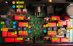
Right, doesn't appear to have any speaker relays. Fairly certain that's why the voltage spike is taking place. One of the Omron G6H DPDT relays is for the standby and stereo/surround options but I haven't figured the other one out. Possibly for the RS232 remote feature but this amp doesn't have that board installed.
After some talking back and forth with Theta, they're working on a schematic for me. Apparently they never had an official one and figured it was about time they did.
After some talking back and forth with Theta, they're working on a schematic for me. Apparently they never had an official one and figured it was about time they did.
No schematic but I do have bias / offset procedures.
Maybe someone can shed a bit of light on this for me.
The pop is gone, assuming the cycling of the standby switch cured that one. I've rewired the outputs with Cardas Litz as well. A little tricky getting that stuff to tin but we figured it out.
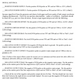
Here is the procedure...
Everything was pretty close to spot on except for the driver offset. They want +.25V but my initial measurement on each of the 2 modules I went through was in the ballpark of -1.5V on both rails. I can't get this to stay stable either. Voltage keeps slowly falling so I need to repeatedly bump it up. Any thoughts of this?
I also plugged both of them in at the same time and one gets warm much faster than the other with no difference in readings.
Maybe someone can shed a bit of light on this for me.
The pop is gone, assuming the cycling of the standby switch cured that one. I've rewired the outputs with Cardas Litz as well. A little tricky getting that stuff to tin but we figured it out.
Here is the procedure...
An externally hosted image should be here but it was not working when we last tested it.
Everything was pretty close to spot on except for the driver offset. They want +.25V but my initial measurement on each of the 2 modules I went through was in the ballpark of -1.5V on both rails. I can't get this to stay stable either. Voltage keeps slowly falling so I need to repeatedly bump it up. Any thoughts of this?
I also plugged both of them in at the same time and one gets warm much faster than the other with no difference in readings.
Attachments
For all future readers of this thread...
To set driver offset, leave the cover on and allow the modules to reach operating idle temperature. Quickly remove the cover and set to +.25V and forget about it.
Apparently with the stages being well isolated and run at a much higher voltage than needed to drive the amplifier, a fluctuation of a few volts is not cause for alarm.
- Status
- This old topic is closed. If you want to reopen this topic, contact a moderator using the "Report Post" button.
- Home
- Amplifiers
- Solid State
- Theta Dreadnaught - Original - Couple Issues