@N101N - you are pretty good at making statements without explanation. "Higher gain = higher distortion".
That would be true of Early voltage distortion, as Early voltage is worse (higher, or more positive for an NPN) with a high gain transistor of the same type.
Is that countered by the higher gain? That depends on the circuit.
A more helpful comment might have been to say that closed loop distortion depends on the open loop distortion and loop gain (i.e. amount of feedback) applied.
That is one reason why I would like to see (at least) three different models for a transistor. A typical model, and models which represent the high gain and low gain limits (not necessarily extremes, but a standard deviation or two from the norm would be very useful).
If the Early voltage is already good then a higher gain transistor may give less distortion overall.
john_ellis,
amplification is distortion. Higher amplification means higher distortion for every reason. The larger the amplification factor, the implanted Cob and the collector-emitter voltage, the larger the collector-base amplitude and the poorer the high frequency response. There is no need to model these relationships. The industrial transistors commonly used in the output stages have a high amplification factor and a huge Cob, therefore and for other reasons predictably develop high distortion, no matter what the simulations say.
Simulations do not provide enlightment, otherwise some people simulating night and day would have infinite knowledge by now. Actually, the more they simulate, the more crappy design they end up with.
Regarding a previous discussion, the magnitude and direction of dielectric polarization in semiconductors continuously undergo a change (by electromagnetic fields). I could not agree with most of your points in that post.
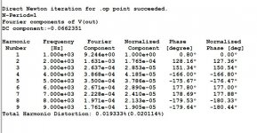
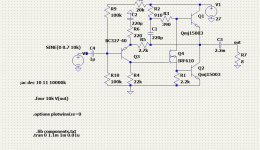
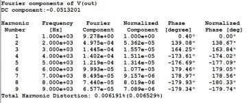
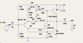
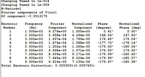
The ccs of 1ma made of lm344 can pull down the distortion to 0.002% for 1k&10k 5.5w. I applied this 2ma in "Sublimed JLH", it has great effect on high frequency character. Rallyfinnen also tried out but he found the high frequencies too much pronounced and he adjusted the current to his taste.
The mjl3281 model doesn't work on Tina, I used the C5200 instead which is about the same.
A current source diode of 1ma can also be used, as now it has 4.6v working voltage.
Attachments
Last edited:
@N101N
Once again, I have trouble with your post. Not so much with the actual technical details but the semantics.
Amplification, by most people's definition, is making a signal larger. That is not distortion as the definition implies "through a linear process". What I suspect you mean is that "amplification by any real device which is not linear introduces distortion". On that basis I can agree that a non-linear device will generate more distortion if it is operating over a larger range. The distortion does depend on the amplitude of the signal swing, or degree of non-linearity a swing covers, not necessarily the amplification.
The output capacitance of a bipolar transistor Cob is not implanted. What is implanted or fabricated are the collector and base regions which then generate a particular Cob. That capacitance is related to a depletion region which can be thought of as a capacitor or dielectric, as you have implied previously, but this is not the whole of the base region – the depletion region is a narrower region which includes part of the base, and part of the collector. This region, as you imply, widens or narrows with the applied voltage. Mostly, it widens as the collector to base voltage is larger than zero volts, and that reduces the capacitance. Being non-linear it will generate distortion in response to an AC signal being applied when the devices are biased with a given DC voltage. The depletion region will "concertina" around its quiescent value. And, yes, modern transistors have fairly large Cob which will generate larger non-linear currents – at higher frequencies. In the audio band, the currents are not so high compared with the base current, for example, for a given output. So while you point to a correct fact, it needs to be put in context of a design where NFB can correct it – and, probably more of a significance, is the effect of large Cob (and because of the emitter structure, even larger Cib) on stability.
I can't take your comments on simulation seriously. You can design with or without simulators. Many designers, I think would say that using simulators gets results quicker than calculating by hand and are sufficiently accurate today to rely on. I'm sure that if you simulated a simple circuit with an ideal transistor model (no capacitances, just the non-linear equations), with another having fixed capacitances and a realistic model, a simulator will show the difference.
Last edited:
But it's not good for the capacitpr's they will dry out very fast because they have the same temperature as the heatsink...Bare copper wire on insulated racks with petals (like 1950)")
There is a pair of JLH 1969M amplifiers (MOSFET variation) and a 36V/5A SMPS to power them. During power on there is a very ugly loud noise on the output, as well as a current spike for a few seconds and then everything settles.
If the voltage is increased slowly using a bench power supply, the problem is mitigated and seems safe for the loudspeakers.
The SMPS cannot be soft started slowly enough to solve the issue, so I'm looking for a solution from the DC side, between the SMPS and the amplifier.
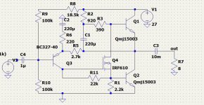
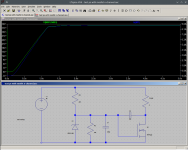
I've read that 36V DC is too high for conventional relays to operate reliably so I fiddle with a possible circuit using a mosfet to ramp up the voltage to the amplifier, as shown on the image.
My knowledge in electronics is limited while I'm climbing the learning curve, so I need some experienced opinions about this idea.
Regards
If the voltage is increased slowly using a bench power supply, the problem is mitigated and seems safe for the loudspeakers.
The SMPS cannot be soft started slowly enough to solve the issue, so I'm looking for a solution from the DC side, between the SMPS and the amplifier.
I've read that 36V DC is too high for conventional relays to operate reliably so I fiddle with a possible circuit using a mosfet to ramp up the voltage to the amplifier, as shown on the image.
My knowledge in electronics is limited while I'm climbing the learning curve, so I need some experienced opinions about this idea.
Regards
Attachments
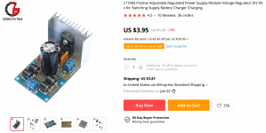
Perhaps try a slow turn-on LDO? Perhaps try the 5A LT1084 in a slow turn on configuration set for minimum dropout? Maybe try 1.5V dropout?
I wonder if a simple capacitance multiplier/ripple eater would have a sufficiently slow turn-on?
LT1083 kits are inexpensive and should be a fairly easy modification to add slow turn-on.
You should also strongly consider a speaker protection board with something like 240VAC/30A relays and a boot delay. I assume you are not using a speaker protection board?
Attachments
Last edited:
Hey Kozard, thanks for replying!
I have a few delay+speaker protection boards available but I don't want to use them in this amplifier because 1)already has a coupling capacitor at the output, 2)sounds clean (to me) and I'd prefer to avoid additional artifacts in the signal path.
The SMPS used is already regulated and smoothed enough with extra CLC filter, so additional LDOs or capacitance multipliers will add unnecessary complexity without obvious benefit, as I understand.
My point is only the slow turn-on, that as you mention, should be a fairly easy modification. Is there any suggested schematic of such modification?
Is the one I posted above valid for the purpose?
Or, alternatively, has anyone successfully solved the issue with the turn-on thump on mosfet variations of JLH 1969? There was some discussion about it in this thread long ago (i.e. page 67) but I couldn't spot any permanent solution.
Regards
*Maybe* increasing the value of the bootstrap cap could calm thing down a bit. This way the current in the output stage goes up slower. However, the input and output caps always needs to be charged when powering up the amp, so I think it will be hard to make it totally quiet.
An ugly way to do it could be to short the output during startup. Nothing in the signal path when the relay is opened, and the inrush current to the output cap should be limited to the Iq setting.
An ugly way to do it could be to short the output during startup. Nothing in the signal path when the relay is opened, and the inrush current to the output cap should be limited to the Iq setting.
Hey Kozard, thanks for replying!
I have a few delay+speaker protection boards available but I don't want to use them in this amplifier because 1)already has a coupling capacitor at the output, 2)sounds clean (to me) and I'd prefer to avoid additional artifacts in the signal path.
I believe that the relay will add totally inaudible and undetectable artifacts. At least several orders of magnitude below the output capacitor.
The purpose of adding the board is to have the boot delay. The amplifier stabilizes before the relays turn on (and thus eliminates the pops and bangs).
A simple solution (a bit like the standby switch on my tube amplifiers) would be two mechanical switches. The first turns on the power supply the second connects the speakers to the output capacitors. You just need to remember to turn them on with the right sequence and a little delay. I am naturally familiar with doing something like this with my tube amplifiers. That is a very simple and low cost solution.
The SMPS used is already regulated and smoothed enough with extra CLC filter, so additional LDOs or capacitance multipliers will add unnecessary complexity without obvious benefit, as I understand.
My point is only the slow turn-on, that as you mention, should be a fairly easy modification. Is there any suggested schematic of such modification?
Is the one I posted above valid for the purpose?
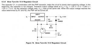
I have several LT1083 regulators and many LM317/LM337. However I have not modified any to slow turn-on since I have the boot delay on the protection boards. However I understand that the slow turn on schematic (that I posted from Ti LM317) works with the LT1083/4/5 also.
I realize that the SMPS might be sufficiently regulated already. That is why I suggested just a minimal drop-out LDO or ripple multiplier setup just for the slow turn-on.
I have experimented with SMPS for my mini1969 and several class AB amplifiers also. So far I have not need additional filters or regulators. I have added additional LC filter sections and I have not been able to detect any difference even when I put my ear close to the tweeter. I have done experiments with the left channel running SMPS and the right running a regular transformer/rectifier/filter caps. I can move back and forth between the two speakers and I have not been able to detect an audible difference.
Or, alternatively, has anyone successfully solved the issue with the turn-on thump on mosfet variations of JLH 1969? There was some discussion about it in this thread long ago (i.e. page 67) but I couldn't spot any permanent solution.
Regards
I don't know of such a solution, but there are many knowledgeable and helpful individuals on this forum and I am sure they will reply if they know of a circuit modification solution.
Last edited:
I would suggest a capacitance multiplier would work. A complementary Darlington pair with MJ2955 and BD139 with the MJ2955 emitter to positive, and a 1mF capacitor from the base of the BD139 to ground, and 1k resistor to positive should work.
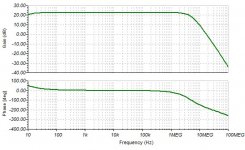
Simulated turn-on thump was 6V peak with the circuit "as is" (at least, my simulated version) and only 0.25V with the slowed risetime.
You will end up with something like a 2V drop across the series pass transistor, perhaps your PSU could be tweaked a little?
Simulated turn-on thump was 6V peak with the circuit "as is" (at least, my simulated version) and only 0.25V with the slowed risetime.
You will end up with something like a 2V drop across the series pass transistor, perhaps your PSU could be tweaked a little?
I realize that the SMPS might be sufficiently regulated already. That is why I suggested just a minimal drop-out LDO or ripple multiplier setup just for the slow turn-on.
I meant "Capacitance Multiplier" or ripple eater. Too late to edit. Sorry about that.
- Home
- Amplifiers
- Solid State
- JLH 10 Watt class A amplifier