It is a great idea to use a boost coil but I might try my power supply at around 20VDC first to be conservative and set bias and see whether I'm happy with the performance. It doesn't need to be too loud in the room I'll be using it in. Mainly in the living room after kids have gone to bed. Its a cold house in winter and could do with some heating.
So should I stick to 1.25A despite the lower voltage for a 6-8 ohm load?
As pointed out I think that a lot of "8ohm" speakers these days are more like 6.5 - 7.
So should I stick to 1.25A despite the lower voltage for a 6-8 ohm load?
As pointed out I think that a lot of "8ohm" speakers these days are more like 6.5 - 7.
I notice that Geoff Moss had made attempts to get replace the 7815 in the 1996 version with 2 transistors as a constant current source.
Why does the 96 version need a constant current source when the 69 version doesn't? And what is the reasoning for wanting to get rid of the 7815. Is it back to the noise concerns people have with these regulators?
Would a CCS add anything to the 69 version?
Why does the 96 version need a constant current source when the 69 version doesn't? And what is the reasoning for wanting to get rid of the 7815. Is it back to the noise concerns people have with these regulators?
Would a CCS add anything to the 69 version?
Is it because of this?
From 1969 WW article:
The current which flows in the output transistor chain (Tr1, Tr2) is determined by the potential across Tr2, the values of R1 and R2, and the current gain and collector-base leakage current of Tr2.
JLH goes on to say that basically as long as heatsink is big enough then current will remain stable.
Modification without 7815 (2/15) by Ulis
http://ldsound.ru/wp-content/uploads/2014/12/Описание-JLH-ldsound.ru_.pdf
http://ldsound.ru/wp-content/uploads/2014/12/Описание-JLH-ldsound.ru_.pdf
Last edited:
Yes, you get about the same figures by extrapolating JLH's tables. Don't forget the other components that are different depending on your supply voltage and speaker options. Generally, if you build it for nominal 4 Ohm loads, it will still work fine with the lighter, 8 Ohm loads but with less maximum power. It's only problematic if you try to drive 4 Ohm loads with an amp. configured for 8.
As you know, speaker specifications are only nominal and vary by many times across the audio band so there is little point to precision here, so long as your calculated values fall on the conservative side with respect to bias current at maximum power and allowable input signal voltage etc.
It's not a big, difficult or expensive project so don't throw in your most expensive parts in the hope of coming up with something extraordinary just yet. Try that when you have the experience and learning of a successful first effort then go on to the next stage")
As you know, speaker specifications are only nominal and vary by many times across the audio band so there is little point to precision here, so long as your calculated values fall on the conservative side with respect to bias current at maximum power and allowable input signal voltage etc.
It's not a big, difficult or expensive project so don't throw in your most expensive parts in the hope of coming up with something extraordinary just yet. Try that when you have the experience and learning of a successful first effort then go on to the next stage
.I notice that Geoff Moss had made attempts to get replace the 7815 in the 1996 version with 2 transistors as a constant current source.
Why does the 96 version need a constant current source when the 69 version doesn't? And what is the reasoning for wanting to get rid of the 7815. Is it back to the noise concerns people have with these regulators?
Would a CCS add anything to the 69 version?
Kawasaki made the fastest motorcycles despite only having two valves per cylinder. That was because they had the highest brake mean effective pressure and did gas flowing on the engine. It was very brave of them to stick with real science. 7815 is a wonderful device that often is misused. The problem is people do not understand the JLH.
It's very likely a set of for motorcycle batteries charged and used in twos ( two on charge, two in use ) would be ideal. A 1uF 100V polyester across them for noise and speed reasons. I often feel car stereos sound better than they should. This could be part of it.
As Ian pointed out keep the batteries in a ventilated place.
I have measured CCSs in many circuits doing far less than people think. A resistor is far superior if the meeting the needs. Strangely where they really work is valve circuits where the valve people don't want to know. They might just use a FET version which for that could be inferior. This is because they believe an FET is more valve like. A transistor as a current amplifier is the best device and a CCS is that type of device. Alas on a purely sceintific bases they aren't always required. It's a bit like vitamin C 30 mg or 1g. Often the attitude is 1g must be better. Some vitamins are toxic in overdose and many do overdose.
I remember a discussion of the very remarkable 1979 Hitachi MOSFET amplifier that had a resistor fed long tail pair input stage of 2SA872a PNP transistors. Many said what a rubbish amplifier. One guy simulated it and said -92dB PSRR. This improved to -132 dB with a theoretical CCS that he was confident no amature could implement. However if a capacitor was added to a split resistor it gave the best of all. Some said that would reduce the linearity. No it wouldn't as it's 95% a current amplifing stage.
Morgan Jones ex BBC writes about CCS in valve designs. Very good reading. I suspect that the BBC had valve equipment that could live or with a few transistors added.
I think Shakespeare said " Most things are neither good nor bad it's what people make of it.". Without the right context a CCS is neither good nor bad. It can completely screw up a design if you get it wrong.
It's not a big, difficult or expensive project so don't throw in your most expensive parts in the hope of coming up with something extraordinary just yet.
Yes good advice thanks. Brand.name output transistors aren't cheap. I was thinking that a 1k variable resistor would be handy for R2 but then checked Mouser and a 1W rated multiturn version is $10. $20 for 2 boards. Might stick with a variety of cheap resistors. It adds up fast thats for sure.
That's where my boss needs me. I find parts that are very good and usually $1. I suspect I more than cover my wages on that alone. I am very fussy and usually say best and cheapest. I have been doing this since about the time of the Moon landings so know parts very well. A very unknown Chinese make Suntan ( yikes ) are very high quality. If you knew how much it pains me to say it that shows I mean it. Be careful of brands. Kia not so long ago was unknown. They now head the list for value. A friend of mine was working on them and had been in Germany before that. He styles the cars. Where I lived he was the only car man not in Formula one. Since this DC joined them about 10 years ago they went from strength to strength. I have a VW Golf. He says he designed the headlights for that. He was so out of work when I met him, he had a basic Renault.
You could try this with a 1K 3W padding resistor. Cheap enough and will get you to where you need to be if given some thought.
https://www.rapidonline.com/Catalogue/Search?Query=multiturn%20pots&Size=20&Attributes={%22Resistance%22:[%222k%26amp%3BOmega%3B%22]}
You could try this with a 1K 3W padding resistor. Cheap enough and will get you to where you need to be if given some thought.
https://www.rapidonline.com/Catalogue/Search?Query=multiturn%20pots&Size=20&Attributes={%22Resistance%22:[%222k%26amp%3BOmega%3B%22]}
I use Sun Tan X2 class caps as valve coupling caps. What makes a capacitor safe also makes is sound good. Companies who sell into both markets charge more for the " good sounding " versions. They are the same.
If you can not find an audio grade capacitor use a high voltage one. Tan theta is usually better. I just put some industrial grade 47uF 250V in a NAD 3020 to replace the over run 63V types. The bonus is they are slightly better devices and what I had to hand. They fit fine. The 3020 is made from very industrial parts slightly over run at 240 VAC. I use Panasonic F range if buying new parts. If polyester 100 V types or greater. The 63 V types are to suit small spaces and not a great choice. 100 VDC mylar are very cheap and good.
I think it does take 40 years to know a good quality part just by looking. Most parts these days are OK if not asked to outperform their designs specs. It's often using the wrong part that matters. Same with motorcars. The wrong oil is often the expensive oil. I bought some EP90 at a farm sales place . Morris 25 litre drum for nearly no money. When asking him about the quality he said " Do you know the price of the equipment that uses this on a farm ". As he said farmers are very fussy and that includes price.
I notice that Geoff Moss had made attempts to get replace the 7815 in the 1996 version with 2 transistors as a constant current source.
Why does the 96 version need a constant current source when the 69 version doesn't? And what is the reasoning for wanting to get rid of the 7815. Is it back to the noise concerns people have with these regulators?
Would a CCS add anything to the 69 version?
On the last point no - the RC decoupling feeding the input transistor base resistor divider network is good enough for setting the midpoint voltage of the output stage ahead of the output capacitor.
The peak to peak level for 10 Watts output is 25.3 Volts so if the midpoint dc voltage ahead for the capacitor is 100mV either way this is not going to affect the power output to any significant degree.
With dc coupling as for the 1996 circuit, that level would be exceeded without some means of increasing the emitter current for the input transistor. With a 7815 the voltage is reliable and the current to be injected can be set by a series resistor.
There is a bypass capacitor on the 7815 output to route and a.c. from noise to earth. In application notes for transient and stability reasons the suggested dielectric is tantalum and sometimes ceramic.
Re Geoff Moss the constant current source in this is for the same purpose. I had sent him the details of that from a Class B circuit published in ETI in 1975 by JLH illustrating circuit.
Apart from an input capacitor this was fully dc coupled throughout and I was interested in the possibilities of adapting this to the Class A amplifier I had built from the 1996 update. Someone got there before me but the idea was not pursued beyond the experimental stage.
Later circuits added a capacitor in series with the nfb earth return arm - this being a backward but apparently necessary step.
The transistors in the current source are nominally at ambient temperature and these have to track one another and probably matched for gain. There is a variation in temperature with a Class A amplifier from ambient to working temperature to contend with. In the end I considered the odds favoured the 7815 approach.
You can take your pick whether to use a 7815 or a constant current source.
As Nigel Pearson has pointed out the 10k tail resistor in the input constant current source voltage reference transistor could be split into series resistors of 5.1k and a capacitor taken from the middle junction to earth - this to improve positive supply rejection.
If you go to Walt Jung's web pages you will find some 101 articles on his take on source designs.
I notice that Geoff Moss had made attempts to get replace the 7815 in the 1996 version with 2 transistors as a constant current source.
Why does the 96 version need a constant current source when the 69 version doesn't? And what is the reasoning for wanting to get rid of the 7815. Is it back to the noise concerns people have with these regulators?
Would a CCS add anything to the 69 version?
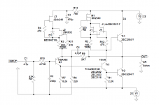
Look at my scheme, I used FETs in CCS instead of bipolars, everything else is the same as in the 1996 scheme.
With FETs I have great experiences from using with tubes and they are generally good for CCS.
In my case after heating the amplifier the offset at the output does not exceed +/- 5mV. I made a version without CCS for the test but this one sounds a lot better. No feedback capacitor is better.
The same effect should be expected with the 1969 version.
As for the 7815, here is the text
The Class-A Amplifier Site - Design Notes
The Class-A Amplifier Site - JLH Class-A Update
Attachments
Constant current sources in reality seldom do as well as they should. Many reasons. They are well liked because they are very cheap to do. In many applications constant current isn't the reason they are used. It's the illusion of being at a seemingly ultra high voltage with an almost infinite impedance. When used with a valve a distortion of 1% might tumble below 0.1% for the same voltage. However a bootstrapped anode load in the same place can be as good. The JLH has this to a lesser extent..
Jung's Tests
The 101 laboratory tests Jung undertook involved a supply of +18volts with an a.c. swept frequency of 1V rms in series. If you compare a figure for THD as 0.1% that is a mere -40dB compared with 90 dB rejection figures for the simplest constant current forms in the tests.
Among other things Jung also looked at cascode JFET options which improved rejection at low frequencies.
grunf is alone in having looked into using JFET s in this way.
I made my first CCS based on these articles about ten years ago.
Before that I have already used DN2540 for CCS around tubes with excellent results.
For small currents I use FETs, and for larger currents depletion-mode MOSFET with FET (s) below.
By the way I am a big fan of Mr. Walt Jung, the regulators in my JLH and Le Monstre are made according to the scheme of his regulator.
Sources 101: Audio Current Regulator Tests for High Performance - Full Article | audioXpress
https://refsnregs.waltjung.org/Improved_PN_Regs.pdf
Attachments
Is that "alone" or "not alone"?....... grunf is alone in having looked into using JFET s in this way.
- Home
- Amplifiers
- Solid State
- JLH 10 Watt class A amplifier