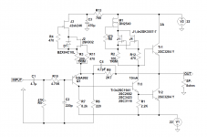
I played with JLH69 for over two years, the starting position was a dual-power version. I then added power sources for Q3 and Q4. I spent most of my time trying out various transistors, primarily for the Q3, which I realized had the most impact on amplifier sound. I dropped the C3 and adjusted the current through the Q4. For Q3, low Cob fast transistors are good.Q3 with low Hfe will not sound good. Q1 and Q2 must have higher Hfe.
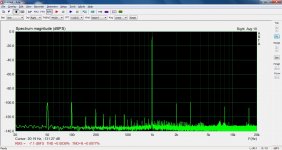
Of the equipment, I only have an oscilloscope and a voltmeter, but on scop I have an FFT analysis and you can see the difference in Q3 selection.
The other important thing is the power supply, it has to be as good as possible with less ripple and noise, initially I only used capacitors, so I added the resistors so I had a CRCRC combination with a 2V voltage drop, now I added the regulators with an additional 3V voltage drop. I have a total of 180,000uF in power supply.
The JLH69 amplifier really sounds great and I have no intention of changing anything for now.
In my opinion it is not necessary to change a lot according to the basic scheme, it is enough to add CCSs, but special attention should be paid to the choice of parts (especially Q3) and power supply quality.
Attachments
....
0.00x% should be possible with some tweaking, but maybe not with the 3055. I have seen figures like that in Arta around 1W into 8ohm load, but I prefer to look at the FFT and not plain numbers. EDIT: not sure now, maybe it was only 0.01 something.. anyway, distortion around -90dB is definitely possible.
Just did a quick test of my PNP JLH to refresh my memory. Load is actually 7.2ohm, not 8.
There are some spikes from noise pickup that should be disregarded at 8kHz and 16kHz, and some 50Hz and multiples of that.
Attachments
Last edited:
Hello you Guys,
I am bulding the high power esl version from Geoff Moss. http://www.kaschei.com/classa/jlheslfig1.gif
I've measures output transistors Type MJ15003 with my Lab-PSU and a thermometer to get the hfe at 85°C. -> Post 5901 Link: https://www.diyaudio.com/forums/solid-state/3075-jlh-10-watt-class-amplifier-591.html#post6083081 ..Thanks for your advice fredbloggstwo!
The transistors have gains between 102 and 129.
Does it make sense to always combine a strong and a weak one on each "side" for Example Q1, Q1A gains = 109 + 125 = 234 Q2, Q2A gains = 104 + 129 = 233.
As far as described in the TCAAS-Design Notes for the 1996 Version the Q1 and Q2 should be matched, Q1 should have higher gain.
Do gains sum up the way I've been thinking of? Is it a "clean" solution? Hope you could give advice! Help would be very much appreciated!
I've been doing some thinking. The JLH design is frustrating because as far as I can tell it was arrived at by experiment and finds a sweet spot that removes the need for an extra stage of amplification. Designs using op amps and current buffers don't give dramatically better paper distortion as proof of concept. The main hang up most seem to have is wanting to use the rules of a class AB designs to update the JLH.This does no harm but when it works is for different reasons.
After some thinking I remembered two designs from the past. Teleton GA202 and PE Texan. The hybrid I suspect could work is the Texan output stage and a single transistor VAS. The output can have any gain you like. This gives options that should favour a gain of one. It might not and most likely will be three. We might have an open loop gain of 700 or greater from two stages.
As the output buffer has massive current gain the VAS current might be lower than usual. 2mA? The distortion of the buffer will be an order of magnitude lower than the JLH. Bias would be two diodes and a resistor. Current between 0.4 to 0.8 amps would be fine as loud stuff would be class AB like old cinema amplifiers. If 0.5 amps 30 watts might be possible. 2 watts class A then AB might sound better than the JLH due to PSU effects.
The big advantage of an amplifier like this is the highly desirable input shunt feedback is used. The beauty of this is if your preamp has the current and the output certainly does the feedback is warp factor 9 fast. I would use the speaker capacitor as bootstrap as 2 mA won't hurt the speaker. It possibly is better.
I always remember tests I did with the OPA604 and this output stage. It was almost impossible to measure any distortion from the buffer if running 0.7 amps bias. If the heatsink large enough the bias was stable with two diodes and a resistor. It's often said this bias method is hopelessly bad. Not really, if so the heatsink is too small. An smps makes that more certain as it is a regulator into the bargain. I suspect even stability will be fine. The output pair can have 100% local negative feedback. Very little loop feedback required to correct it. The distortion is a single transistor with active current source with a gain of twenty perhaps. The current source makes the transistor think it's working from hundreds of volts. Therefore the amplification curve looks like a straight line. An mpsa 44 at 300 VDC no better if as good.
The JLH still assumes a valve preamp would be used. This Idea assumes a preamp that might drive 32 ohms used. One might even make the amplifier gain of minus three and make the preamp work harder.
nigel, you noted Douglas Self said
Well, it isn't really, because the current split is dependent on the current gains of the two transistors. So if you know the gains of the transistors as a function of current you can determine the split. And many JLH builders might well know the gains because of the stipulation that the higher gain device should be in the lower position.
In this case the higher gain transistor does most of the work, since a small change there creates a larger change than in the upper transistor. That would give rise to rallyfinnen's imbalance.
If they are matched, then for small signals the currents share equally. At higher currents then the transistor with the higher gain once again carries more of the current than the one with the lower gain, so this gives rise to second harmonic distortion. Or would, except for the second half of the signal waveform the situation reverses, so cancelling, largely that distortion.
Those older transistors which have a large gain variation with current required the Iq to be set at half the peak base current needed to fully drive the lowest gain transistor at the highest output current. Then, since the gains increased at lower currents than at peak output, the Iq sat higher than the ideal value. Modern linear gain transistors would be much better in this respect.
However, to ensure that the currents do split equally and over a wider range, emitter resistors and base bias resistors should be used, as I have done. For that very reason. But as we have noted, overall distortion may increase because of the loss of OLG.
.that the current division is vague
Well, it isn't really, because the current split is dependent on the current gains of the two transistors. So if you know the gains of the transistors as a function of current you can determine the split. And many JLH builders might well know the gains because of the stipulation that the higher gain device should be in the lower position.
In this case the higher gain transistor does most of the work, since a small change there creates a larger change than in the upper transistor. That would give rise to rallyfinnen's imbalance.
If they are matched, then for small signals the currents share equally. At higher currents then the transistor with the higher gain once again carries more of the current than the one with the lower gain, so this gives rise to second harmonic distortion. Or would, except for the second half of the signal waveform the situation reverses, so cancelling, largely that distortion.
Those older transistors which have a large gain variation with current required the Iq to be set at half the peak base current needed to fully drive the lowest gain transistor at the highest output current. Then, since the gains increased at lower currents than at peak output, the Iq sat higher than the ideal value. Modern linear gain transistors would be much better in this respect.
However, to ensure that the currents do split equally and over a wider range, emitter resistors and base bias resistors should be used, as I have done. For that very reason. But as we have noted, overall distortion may increase because of the loss of OLG.
I had a go at Mr S over current mirrors saying that the ones in his books don't exactly work as well as stated. I recommend BDV61/62 as they work as would be wanted and are cheap. As they seldom see two volts they can be used ( not even one ) The reason is the Self designs use the VAS hard connected to the rail. I only mention this as it's shades of the same critism. Mr S likes to think his advice is about assembly lines making amplifiers. The imbalance is due to a one sided VAS drive with asymmetrical sourcing and sinking of current. A one legged cyclist. The ultra simple Hitachi design avoids this. A beautiful sounding amplifier. Almost every part of the Hitachi is held up as an example of how not to do it. I doubt the critics ever heard one and the measurements are supurb.
I did a little more thinking about my Rod Elliot El Cheapo PE Rhondo hybrid. The El Cheapo is open loop gain of 180 and the Rhondo output stage 10. That's 1800 before trying. I would imagine 5000 is possible both in voltage and current terms. Rod gets 0.14% THD. I have a hunch 0.01 could be possible if stability isn't an issue. Class A to 2 watts and 30 watts in AB. I have no Idea why El Cheapo has such a low gain. This amp should sound nice on simple AB. I am listening right now at 1 watt. It's loud. If a temperature it would be 23C.
I did a little more thinking about my Rod Elliot El Cheapo PE Rhondo hybrid. The El Cheapo is open loop gain of 180 and the Rhondo output stage 10. That's 1800 before trying. I would imagine 5000 is possible both in voltage and current terms. Rod gets 0.14% THD. I have a hunch 0.01 could be possible if stability isn't an issue. Class A to 2 watts and 30 watts in AB. I have no Idea why El Cheapo has such a low gain. This amp should sound nice on simple AB. I am listening right now at 1 watt. It's loud. If a temperature it would be 23C.
Last edited:
I tend to use fully symmetrical VAS stages too. I also like to use DC coupling throughout and single VAS or "quasi-Darlington" VAS (before some critics say it isn't a real Darlington- I'd say the idea is to multiply the current gain, the essential point) have a lot of thermal drift - because they are not balanced.
DC coupling throughout avoids any capacitor distortion, not necessarily because of needing DC!
DC coupling throughout avoids any capacitor distortion, not necessarily because of needing DC!
I think I know that idea. A Serbian friend wrote me about it It loos like a Darlington.
My idea has the possibility of a complimentary feedback pair VAS. I tried one before and thought it wasn't very different to the single device and maybe a tad bland. That probably was lack of second harmonic. Anyone who has heard the Rega Brio amps might not choose this route. It is a Texan/Rhondo. With some helpful curve distortion it might work.
My idea has the possibility of a complimentary feedback pair VAS. I tried one before and thought it wasn't very different to the single device and maybe a tad bland. That probably was lack of second harmonic. Anyone who has heard the Rega Brio amps might not choose this route. It is a Texan/Rhondo. With some helpful curve distortion it might work.
I have been tweaking the crossovers on a pair of Troels C17 speakers I built some years ago. I have been using active filters for them for some time, but now I re-tuned the passive XO, and they are now starting to sound really nice to my ears. I have not really considered using the PNP JLH for these, since they have two woofers in parallel and dip to abt 3 Ohms around 200Hz.
Anyway, the point is that I gave the JLH a try, and I was really surprised how nice it sounded on these speakers. Even if it has some problems with bass, especially on higher volume, it still sounds significantly better on low volumes than any other amp I tried. Maybe it's helped by the fact that impedance stays around 8ohm and above in the higher registers. I guess I should try to finish the -96 version with dual outputs, it should be better at driving these speakers..
Anyway, the point is that I gave the JLH a try, and I was really surprised how nice it sounded on these speakers. Even if it has some problems with bass, especially on higher volume, it still sounds significantly better on low volumes than any other amp I tried. Maybe it's helped by the fact that impedance stays around 8ohm and above in the higher registers. I guess I should try to finish the -96 version with dual outputs, it should be better at driving these speakers..
Often when active the crossover can be the amplifier. I put an active filter inside the amplifier feedback loop then used the coupling capacitors as the protective second pole. My old speakers crossed at 250 Hz and 6 kHz.
My NAD 3020 was only supposed to be a stand in until I got use to the new house. It has a wacky phono stage now. I suspect I like the Krell less than the NAD. I only ever heard one settup that impressed.The Preamp by Tim de Paravacini and Linn Isobaric. It was stunning and unlike other encounters. The Isobaric was a KEF kit three times two.
My NAD 3020 was only supposed to be a stand in until I got use to the new house. It has a wacky phono stage now. I suspect I like the Krell less than the NAD. I only ever heard one settup that impressed.The Preamp by Tim de Paravacini and Linn Isobaric. It was stunning and unlike other encounters. The Isobaric was a KEF kit three times two.
Douglas Self shows how electrolyte capacitors used carefully do not cause distortion. Chris Bateman did other work. Putting the two together says use big values and keep polarising voltages below 0.4V or 0.25 Vrms. The bootstrap capacitor under typical 1 watt listening can be this way. People are often surprised how good the bootstrap is. Self recommends using the input capacitor to set bass preference. It can be a film type.
One unusual consiquence of this is a compromise of feedback and capacitor distortion might arise. I suspect ear distortion more likely. The sound difference can be noticeable when wrongly chosen. Never use the trick of half voltage rail capacitor bias unless forced to. Use a film type.
I have been thinking about sound of fast transistors. I think the issue is the lower side power transistor can be tweaked with the 2k2 charge dissipator. Use 50 kHz square wave and dummy loud at 2 Vrms. Tweak the symetry. Mostly it could be only this that matters. This is an unusual Darlington so needs optimum discharge of the pn junction space charge due to minority carriers. Diode noise is the collapse of this field. This charge is greatly assisted by being class A. I could imagine removing the resistor a possibility. A forward biased transistor is a fancy low grade resistor. It is possible the 2K2 is to assist start up. JLH forgot to say all the ideas he didn't use and why.
There is always a dilemma in speeding up transistors. Using fast ones in the first place helps. But to turn them off quickly means removing base charge. Without a resistor there is nowhere for it to go, so that will always be the slowest case. Ideally, you would aim to generate a reverse current equal to the forward current for an optimum trade-off. For the old slow 2N3055, if the peak base current touched 200mA then that implies having a base resistor of just 3 ohms unless it could be attached to a negative voltage (not too great though because of BVebo limits). The other point about this is that the reverse current only needs to be applied until the current has dissipated. Perhaps for one microsecond. A 3 ohm resistor is therefore going to waste power most of the time.
Self once mentioned that the old 2N3055 circuit (a class AB classic) showed an increase in current at high frequencies (only 30kHz). I too had seen that and cured it with a 10 ohm resistor instead of the usual 100. The JLH could benefit from a negative supply rail to speed the lower transistor up, but as I've said previously, the slew rate is more a problem with the upper transistor when turning on, because it only has its own frequency response to drive it (that is, in the original JLH 10W with bootstrap). A driver transistor that could nudge the current up would help there - or, simpler, using fast transistors.
Your other comments about keeping voltages low on electrolytics which may get reverse biased is valid, as Self suggests. A fully DC coupled circuit though avoids LF time constants in all forms, such as overshoot to a transient, let alone capacitor distortion. Having said that I would still probably be OK with a single capacitor coupling - just one, but then there are the preamp considerations...
Last edited:
Very interesting John. Too many times people do all the right things for all the wrong reasons. That's called ritual.The best example is antibiotics against viruses. It's secondary infection that they can work against. Valid if understood. I recommended HIV drugs against CV19 to the local surgery. I read WHO are trying that. I don't claim I caused that.
It seems to me too, that fast (and linear gain) output transistors sound better in the JLH.
Today I made a quick test setup to try the high power version I have. It had more drive to drive lower impedance (bass), but it also has the 15003 outputs, and somehow the treble reminds me of my JLH69 (white boards) which also has 15003 outputs. The PNP version with fast and linear outputs just sounds more open and detailed in the treble, and upper mids too.
The test setup is far from perfect, I used a switched supply with +-26V forcing me to run at abt 0,8A/device, and still slowly overheating even with fan cooling. However, the test makes me wonder if it's worth doing a 'proper build' with that setup. If so, I would like to do it with separate linear power supplies(dual mono), and that would make it a really expensive build (cap banks). I suspect I might end up with a heavy and expensive box sitting on a shelf collecting dust..
Somewhere in the back of my head I have this idea of a higher power version with double 2sa1216 outputs.. just more of what I have and like, so to say. Maye I should try some simulations on that.. Then again, adding outputs would probably be a compromise too, with more capacitance in the devices to charge and discharge, but I still feel it could do better than multiple slow devices.
Great to hear that the JL-H is still arousing interest.Split rail amp. is much better,eliminates the op. cap. Tried building the amp. with Toshiba 2SC5200s (watch out for fakes!). The sound was extremely "bright",not surprising as the op. was still flat at 250KHz.!It is well worth reading the JL-H section on the Class A Amp. Site. now hosted by Elliott Sound Products.
There are a few points to make about replacing 2N3055 with 2SC5200 firstly there is no need for a compensation capacitor using the former as the low fT sets the dominant pole of the whole amplifier. JLH stated this in his book.
If you use 2SC5200 then you have to rely on the voltage gain stages having enough diffusion capacitance for Miller effect to reduce the gain to unity before the phase reaches - 180 degrees.
Having culled the main stability of the original design it makes sense to do some calculations in that regard or stick to the script. If people expect improvements in sound without doing this they will perceive the change as an improvement.
As loudspeakers generate delayed signal there is a need for a margin of 45 degrees to trouble can start moving above -135 degrees. If the sound is extremely bright there has to be a stability issue.
There is a set of articles on Rod Elliott's site on the follow up Class AB amplifier by JLH in 1970 based partly on the 1969 Class A.
I suggest you study his preferred method of stability compensation. He did not support the use of lead capacitors that some have included in the feedback path - he said these made the 1969 Class A design "readily oscillatory". Bob Cordell has also cautioned against the use of lead capacitors in the feedback path.
My Indian 3055 required some Millar capacitance to the driver. 33pf collector to bass. I suspect less would have been OK. The driver bc337-40. On reflection the bc337 was a bit marginal at 0.6 watts. The higher gain fake 3055 made it possible. When I say fake a very superior fake. Having read JLH on compensation I tried everything. Nothing except the Vas worked. JLH talks about output to input. I didn't find that workable. The brightness heard is doubtless instability. It's said marginal instability sounds great. Reason is music is less punishing. Some think the signature of the amplifier can be inferred by rise time or decay time.
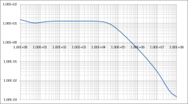
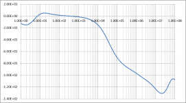
mjona offers good advice and it is instructive to compare the performance of the JLH 10-watter with different transistors. I ran a Tien anaylsis on four configurations: (1) with a 2N3055H (the slow hometaxial base device) model; (2) with a 2N3716 (epi base) model; (3) with a C5200 model and (4) a C5200 with a small compensation capacitor. Rather than showing all of the plots, here are the first two showing the loop gain and phase of the first. (a) shows the loop gain and (b) the phase.
The results are summarised as:
Configuration Gain margin Phase margin*
1 40dB 90°
2 26dB 68°
3 26dB 74°
4 30dB 95°
* Where the phase has not reached 180 degrees, I have taken the margin at a point of inflexion.
These are what the plots show, at least. I have not checked the C5200 model, but I have generated the 2N3055H model as none of the available ones I have seen describes it properly, and adjusted the 2N3716 model to what I think seems a better representation than the commercially available model I had.
The first result confirms that the original design with slow devices has the best overall stability margin. All show that they are stable, however. What is interesting is that the high speed devices do not appear to require a capacitor, but the epitaxial devices (4Mhz types) have a lower phase margin than the very high speed C5200.
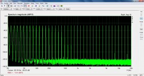
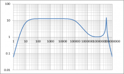
The compensation capacitor for (4) was a small value of 33pF. And I think this is where some of the generalisations about using it need to be considered more fully. If using capacitors to roll the gain off at some particular (lowish) frequency, there are several consequences. First, it will indeed reduce the gain at the target frequency (as set by the RC time constant) but the gain in a non-inverting feedback loop does not get to fall below unity until the open loop gain has. The gain therefore could well flatten out, hovering just above unity into the megahertz region, which means it does not necessarily compensate as one might have expected in terms of stability improvement through reducing the gain. This point is well worth illustrating. The third picture show the frequency response of the high speed version where a 560pF capacitor has been added as a compensation capacitor in an attempt to limit the response to 100kHz. The horrid spike is clear evidence of trouble. The Tian plot confirms that the gain margin is -3dB (that is, none - it has positive feedback) and the phase margin is, well, none either as it is a degree or two over 180.
A small capacitor which has less effect on the output stability can sometimes be used for a small phase correction. Even Doug Self indeed included one in his "Blameless" design. Configuration 4 confirms that there is indeed a greater phase margin with the capacitor. From these results, which I think I would need to check, it does indeed seem that a small capacitor can provide an improved margin.
What might be even more significant, however, is the unity gain frequency. This is 21MHz (simulated) for the high speed device with and without the compensation capacitor. That has significant consequences for layout. Any stray inductance in the leads (power supply, loutspeaker wires, grounding) could potentially cause instability. This may well leave the circuit open to potential parasitic induced oscillations.
Possibly, this excessive frequency response may well be the cause of varying results when using a compensation capacitor. If I include a small compensation capacitor, then invariably I will also use an output RC-LC network on the output which acts to counter stray speaker wiring inductance and also reduces potential RF pick up getting into the amplifier through this capacitor.
My conclusion is that a phase lead feedback capacitor is certainly not something which can be used lightly. That raises the question as to what can be done to ameliorate an excessive gain at megahertz frequencies when using these modern transistors. One traditional idea is to add "sprog stopper" capacitors. Adding 100pF between the collector and bases of the output transistors brought the unity gain frequency down to 10MHz, but at a closing rate of 40dB/decade which is considered marginally stable. Another option is to add 100 ohm resistors in series with the bases, and combining both gave a well controlled gain reduction, but still at too fast a rate. To compensate for the 12dB/octave roll-off a phase lead capacitor was also added. The phase margin became 100 degrees while the gain margin was 30dB, and the unity gain frequency was as mentioned 10MHz.
In square wave testing the result into a resistive load was as clean as expected, with no overshoot or ringing on the leading edges. Nor was there any sign of trouble with a 200uH and 5 ohm series "loudspeaker" equivalent.
Maybe the next action would be to test this on the bench.
The results are summarised as:
Configuration Gain margin Phase margin*
1 40dB 90°
2 26dB 68°
3 26dB 74°
4 30dB 95°
* Where the phase has not reached 180 degrees, I have taken the margin at a point of inflexion.
These are what the plots show, at least. I have not checked the C5200 model, but I have generated the 2N3055H model as none of the available ones I have seen describes it properly, and adjusted the 2N3716 model to what I think seems a better representation than the commercially available model I had.
The first result confirms that the original design with slow devices has the best overall stability margin. All show that they are stable, however. What is interesting is that the high speed devices do not appear to require a capacitor, but the epitaxial devices (4Mhz types) have a lower phase margin than the very high speed C5200.
The compensation capacitor for (4) was a small value of 33pF. And I think this is where some of the generalisations about using it need to be considered more fully. If using capacitors to roll the gain off at some particular (lowish) frequency, there are several consequences. First, it will indeed reduce the gain at the target frequency (as set by the RC time constant) but the gain in a non-inverting feedback loop does not get to fall below unity until the open loop gain has. The gain therefore could well flatten out, hovering just above unity into the megahertz region, which means it does not necessarily compensate as one might have expected in terms of stability improvement through reducing the gain. This point is well worth illustrating. The third picture show the frequency response of the high speed version where a 560pF capacitor has been added as a compensation capacitor in an attempt to limit the response to 100kHz. The horrid spike is clear evidence of trouble. The Tian plot confirms that the gain margin is -3dB (that is, none - it has positive feedback) and the phase margin is, well, none either as it is a degree or two over 180.
A small capacitor which has less effect on the output stability can sometimes be used for a small phase correction. Even Doug Self indeed included one in his "Blameless" design. Configuration 4 confirms that there is indeed a greater phase margin with the capacitor. From these results, which I think I would need to check, it does indeed seem that a small capacitor can provide an improved margin.
What might be even more significant, however, is the unity gain frequency. This is 21MHz (simulated) for the high speed device with and without the compensation capacitor. That has significant consequences for layout. Any stray inductance in the leads (power supply, loutspeaker wires, grounding) could potentially cause instability. This may well leave the circuit open to potential parasitic induced oscillations.
Possibly, this excessive frequency response may well be the cause of varying results when using a compensation capacitor. If I include a small compensation capacitor, then invariably I will also use an output RC-LC network on the output which acts to counter stray speaker wiring inductance and also reduces potential RF pick up getting into the amplifier through this capacitor.
My conclusion is that a phase lead feedback capacitor is certainly not something which can be used lightly. That raises the question as to what can be done to ameliorate an excessive gain at megahertz frequencies when using these modern transistors. One traditional idea is to add "sprog stopper" capacitors. Adding 100pF between the collector and bases of the output transistors brought the unity gain frequency down to 10MHz, but at a closing rate of 40dB/decade which is considered marginally stable. Another option is to add 100 ohm resistors in series with the bases, and combining both gave a well controlled gain reduction, but still at too fast a rate. To compensate for the 12dB/octave roll-off a phase lead capacitor was also added. The phase margin became 100 degrees while the gain margin was 30dB, and the unity gain frequency was as mentioned 10MHz.
In square wave testing the result into a resistive load was as clean as expected, with no overshoot or ringing on the leading edges. Nor was there any sign of trouble with a 200uH and 5 ohm series "loudspeaker" equivalent.
Maybe the next action would be to test this on the bench.
Attachments
One problem is testing with a real load. Sometimes it would be worth buying a reasonable old speaker and ear defenders. Using music as your guide try 1 kHz 5 watts and 10 kHz 0.5 watts. Whilst it wouldn't tell you everything it would be realistic. Hopefully my Whafedale Lintons will tollerate that. I would insert a 0R1 to look at the current also. I have some Dynaco A25 that are too precious for this.
The guy who advocated marginal stability gave two possibilities. One is the conditions suits real music better. The second is transient exaggeration the never reaches oscillation adds sparkle. Self warns against undamped output inductors as causes of wild goose chases. He thinks many hi fi magazine test results do not realise this. The JLH has no such devices nor Naim amplifiers of old. My little class D has none. Music in antiphase and carrier in phase. That's genius. The bridge also reduces bus pumping. The speaker inductance mops up the tiny 250 kHz residual. An optimist 1.65 watts from USB.
The guy who advocated marginal stability gave two possibilities. One is the conditions suits real music better. The second is transient exaggeration the never reaches oscillation adds sparkle. Self warns against undamped output inductors as causes of wild goose chases. He thinks many hi fi magazine test results do not realise this. The JLH has no such devices nor Naim amplifiers of old. My little class D has none. Music in antiphase and carrier in phase. That's genius. The bridge also reduces bus pumping. The speaker inductance mops up the tiny 250 kHz residual. An optimist 1.65 watts from USB.
Oops - I meant CR-LR network. I would not use an undamped inductor, ever.
Yes, inductors need damping, and real loudspeaker systems have challenging combinations of RLC in the crossover networks. I'm not claiming this is the optimum solution, just that compensation capacitor usage can well be tricky.
I woudl think that most Class D amplifiers would use a filter, though I saw some cheap low power ones stating that they rely on the loudspeaker impedance to oppose the switching signal. I would not trust that with anything more than perhaps 1W!
JLH didn't need it- but most of the time they are fitted for ELS speakers, of which very few people actually use.
Last edited:
- Home
- Amplifiers
- Solid State
- JLH 10 Watt class A amplifier