Not strange, the JLH69 design I built with 2SC5200's did not need a cap either, only using MJL3281A. BUt I think this just shows some marginality, meaning different fT devices could change the results. As mjonas said.
If you simulate the JLH 69 circuit with a 220pF feedback capacitor and 2N3055's (approx 3MHz) there is a nasty peak at around 20MHz. That disappears using 22pF. The peak is worse using MJL3281A's and 2SC5200's, but I only needed compensation in reality using the MJL's.
Another source of oscillations is in the power supply leads. These must be, even for medium frequency devices (like the (new) 2N3055) short (between PCB and filter cap). A 100 or 220uF across the power supply pins on the PCB may help in the case that they are too long (which Dr Bailey first pointed out in his 30W design) which as I can confirm means more than 100mm.
All of which says that layout can be as important as circuit design. Especially when the frequency response is high as anything can then become dominated by parasitic C and L.
Ok, note taken ")
I've started to convert the mentioned Zerozone PNP 1969 amps to floating ground too, since I tried it on the standard version and it made a significant improvement on the bass. I intend to do some adjustments on resistor values too, to get balance/cancellation of the output devices, but not a full 'sublimed mod'.
I can almost do it 'for free' on these boards since they came with rectifier and a lot of caps. I just have to do some re-routing & minor cutting on the PCB to use the caps for the floating ground.
If you can do that rebalancing by spectrum analyser you can order the harmonics. If they fall like a ski slope theory says it will sound neutral and open. If the odd harmonics slightly raised the sound seems faster. The later usually is acceptable to many. It might seem more powerful. My JLH point to point wired measured exactly to the ideal. Often what guess to be balanced isn't. With the jlh it's worth doing as the current source is complex. I think jlh said I should be the higher gain device. If true that's the opposite of what I guessed.
Perhaps floating ground works as it keeps the preamp free of ground plus Power amp noise. It could be RF related. I doubt that as it's class A. Floating a Linn Valhalla power supply reduces mains ripple beat noise by 6 dB. It's only -40 dB and peaks at -60 dB after mods. If floating the JLH is better it might indicate some ripple. Remember ripple has a wider spectrum than the original mains sine wave. As someone said a choke capacitor power supply has virtue. If floating helps it's much cheaper. Remember if your power amp floats but your preamp is grounded then your power amp is grounded. That option might still sound better as it relocates the ground zero volts reference point. Again a spectrum analyser will tell you. Balanced inputs like public address amplifiers can minimise these problems as ground tries not to pass current when a signal ground. If relocating grounds look for harmonics verses quantity. For example you could get -80 dB 50 Hz or -86 dB with many harmonics. The -80 dB might sound best. Rotating the transformer might get this result. Hum nulling or hum bucking.
The internet has freeware spectrum analysers using the computer sound card. Surprisingly most sound cards good enough.
Last edited:
Yes, I have done the balancing with spectrum analyzer (FFT in ARTA). Usually 2nd and 3rd end up on the same level at around -80dB I think, and start rising when getting closer to maximum output. Usually I look more at the IMD spectrum when I do this, with 13+14kHz input.
I'm running them with separate switched 19V laptop supplies(7A rating), and the noise levels are much lower compared to linear supply. What I see is picked up by my measurement setup, and that is at abt -100dB.
I'm running them with separate switched 19V laptop supplies(7A rating), and the noise levels are much lower compared to linear supply. What I see is picked up by my measurement setup, and that is at abt -100dB.
It does pay to keep an open mind. A friend of 24 years brought me the power supply of his Garrard 501 turntable. A round trip of 220 miles.. I was exceedingly luckey it was a simple repair. We then went to KFC to get some food. When we came back we checked the data. I was able to tweak it a little. Most interesting was the oscillator at 49.9109Hz +/- 0.002%. Not bad for 20 plus years. It is a very low distortion supply with a class AB amplifier.
I'm getting confused with what threads I should write in.. but I guess this is general JLH territory, so I'll post it here..
I did some distortion measurements and tweaking on the PNP version with floating ground. I put in a trimmer instead of R25, to be able to tweak Iq and the balance between the output transistors independently.
Schematic is here for reference: https://www.diyaudio.com/forums/solid-state/3075-jlh-10-watt-class-amplifier-557.html#post5878433
What I found was that there was a optimal (for low distortion) setting based on Iq, not based on the balance between the trimmers r25/R26. I got the lowest distortion around 1A Iq. Not sure why this is, maybe has something to do with current in driver etc?
Could be gain verses current. I think people should take the floating thing as important. This is interesting.
I have a little class D 1.7 watt amplifier powered by USB. It is a bridge type. It has taught me a lot about what really matters. One could have two current modes. 1 amp and 1/2 an amp. The thing is 1/2amp would suit my TV listening. I imagine it might sound better for up to 90 dB sound levels. Class D can mimic class A. It has no conventional crossover distortion.
I have a little class D 1.7 watt amplifier powered by USB. It is a bridge type. It has taught me a lot about what really matters. One could have two current modes. 1 amp and 1/2 an amp. The thing is 1/2amp would suit my TV listening. I imagine it might sound better for up to 90 dB sound levels. Class D can mimic class A. It has no conventional crossover distortion.
PNP version looks completely mad at first. One reason it could work is PNP seem to have better current gain. It's surprising how well matched NPN and PNP can be if looking into the science. 2N3055E and MJ2955 come to mind.
I think JLH said a Darlington could be used on the bottom output transistor. TIP142 and 147 could be considered ( one is N other P ). He said lower distortion results. Modern Darlingtons are fast enough. MJ3001 and 2501 from memory in T03. These I suspect are slower. It would be interesting if despite the poor Ft a Darlington sounds better. I suspect it will. Spectrum allowing when measured. Remember this is not a class AB amp. The feedback loop is continuous.
Mike Creek thought hiss alone helps AB work. Very likely. Thus don't go too far with low hiss. -80dB would be fine for any. This might sometimes favour analogue CD or tape source. It could be helping the AB amp switch. Thus the softness might be a type of dithering. The first Creek 4040 was by accident pure class B. It sounded reasonable. Mike learnt from this. I forget how many CAS4040 my brother upgraded. FM Nicam can not work correctly without hiss. -78dB to -75dB. 3 dB of magic.
Hope someone will be able to use this?
http://www.farnell.com/datasheets/468663.pdf
https://cpc.farnell.com/unbranded/t...&ddkey=https:en-CPC/CPC_United_Kingdom/search
I'm getting confused with what threads I should write in.. but I guess this is general JLH territory, so I'll post it here..
I did some distortion measurements and tweaking on the PNP version with floating ground. I put in a trimmer instead of R25, to be able to tweak Iq and the balance between the output transistors independently.
Schematic is here for reference: https://www.diyaudio.com/forums/solid-state/3075-jlh-10-watt-class-amplifier-557.html#post5878433
What I found was that there was a optimal (for low distortion) setting based on Iq, not based on the balance between the trimmers r25/R26. I got the lowest distortion around 1A Iq. Not sure why this is, maybe has something to do with current in driver etc?
To continue on this subject, I did some tweaking and emasuring today, and found the distortion went down if I increased R25 but maintained abt 1A. Now I installed a 220ohm resistor, and 2nd & 4th harmonics came down to really low levels, but there is a 3rd that is higher than expected, around -80dB that is constant no matter how I tweak Iq.
Jean Hiraga said that the best sound has second harmonic above third. Third above fourth as so on. Hiraga speculated the curve should be falling exponential. If thd is <0.1% and exponential harmonics it will have zero perceived distortion. This was the 1980s and he may not say that now. His amplifier Le Monstre is the definitive alternative to the JLH. My admiration for the JLH is very standard components with elite performance. Hiraga has always been my inspiration.
I have read similar statements too. I'm not in a position to say what I prefer. I only have a clue that it might depend on the music.
Does anyone have any clues to where the 3rd harmonic could be coming from in the PNP amplifier? It seems unrelated to Iq and the 'balancing' of the output transistors, this seems to affect the even harmonics, but not the third. Other odd harmonics are low, but the 3rd stands out at about -80dB. IMD is low at abt -100dB.
Could it be component choices?
(schematic: https://www.diyaudio.com/forums/solid-state/3075-jlh-10-watt-class-amplifier-557.html#post5878433)
Last edited:
The 3rd was not influenced by the resistor values I tweaked, so I'm hoping somebody would have an idea where it comes from, so I could tweak it.
It stays about constant at -80db under the input signal, until the amplifier gets close to maximum load, then distortion increases overall.
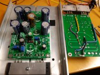
However, I must say first impression is that it sound pretty good. Maybe even better than the white board with floating ground and MJ15003 outputs. It's also quite practical that everything is mounted on the PCB with some modifications.
It stays about constant at -80db under the input signal, until the amplifier gets close to maximum load, then distortion increases overall.
However, I must say first impression is that it sound pretty good. Maybe even better than the white board with floating ground and MJ15003 outputs. It's also quite practical that everything is mounted on the PCB with some modifications.
Attachments
If I had to I'd start by looking at variations in beta (gain) for various transistors. Plus (as suggested by others) having a look at the spectrum of distortion productsI got the lowest distortion around 1A Iq. Not sure why this is, maybe has something to do with current in driver etc?
Yes, I have looked at the spectrum, but I don't know how to interpret the result
Both channels are as good as identical, so I would rule out beta variations between transistors based on that? Or do you refer to linearity int the operating range, beta groups etc?
The PNP output transistors are very linear according to spec, but they are probably fakes, and I have not measured the linearity myself..
I must say I really like the sound from these PNP amps as they are now. More than the white NPN boards. I have listened to them a lot now, and no headaches or 'fatigue'. I tend to get headaches with some amps. It opposes logic, but it sounds like the PNP boards with only 1A Iq have better defined bass, better transients and sound more 'effortless', detailed but yet relaxed. I like that.
I was actually about to dampen the tweeter a bit in the XO before, but with the PNP amp they sound just right, not irritating to my ears. Speaker measure slightly sloping down as I usually like it, and yes, frequency response is flat from the amp, and the speaker is an easy load in the highs.
I did try to 're-tune' the white NPN boards today. I found another setting at just over 2A Iq where IMD was very low, and when looking at the 1kHz it had the falling trend on the harmonics (third was at the same level as before, but 2nd & 4th was higher). Easy to achieve the falling trend on the harmonics with a single tone, but getting low IMD at the same time took some tweaking.
After listening to them, I can't say I liked the sound better than before with lower 2nd and 4th (same IMD). Maybe sounds a bit softer with higher evens, but somehow more 'muddy' too /not as clear.
Well, a lot of rambling here, but I'm a bit confused about what (I think) I hear and what I measure, because I can make them both measure pretty equal, but they still sound different.
The amp design can probably be significantly improved by bootstrapping the first transistor's collector, which would increase the open-loop gain available for the feedback to use. The emitter of the 2nd transistor can be used to bootstrap the R22 load (split it in half and drive the centre from this emitter via a capacitor).
The series feedback via the input transistor's emitter leaves the Vbe of that transistor uncorrected by feedback, and that's a source of every harmonic. Decreasing them at the source will mean you won't need to try and cancel them later in the circuit (you can only cancel one harmonic at one amplitude at a time...)
The less the current through the first transistor is affected by the input voltage the better for its linearity - so bootstrapping its collector load is a great place to start improving performance. Or add a constant current load in place of R22.
I'm going to party like it's 1999 (+3)
Start reading from there. (There's only 500 odd pages to get through. The Beyond the Ariel thread has nearly three times that to wade through). Pretty much any possible design variation has been tried or discussed somewhere in this thread.
I refer you back to 2002 and post #91The amp design can probably be significantly improved ....
Start reading from there. (There's only 500 odd pages to get through. The Beyond the Ariel thread has nearly three times that to wade through
). Pretty much any possible design variation has been tried or discussed somewhere in this thread.Member
Joined 2009
Paid Member
maybe not in this thread though - what Mark suggests is something I used for my TGM8 amplifier. I was thinking about using it on the JLH. Just weird that Mark posted the same thought only a week or so after I was mulling it over. There must have been just enough clues along with both of us reading similar things over the past months that our thought processes had commonality. I've seen this before on the forum where people have come up with similar suggestions but not always so closely time-aligned.
Ah, but the reason for the JLH amplifier's popularity is it's particular spread and level of distortion products and of course, its simplicity. If we change those features to fix what may be considered lacking or wrong about the design, we may as well have started out with a "blameless" type of class A amplifier instead. Then I'd ask myself why I did that when I actually was seeking a sound quality akin to Hiraga's preferred distortion harmonic profile in the first place. Perhaps like JLH himself, I should seek the preferences of a panel of listeners rather than rely on purely technical appraisals.
This link is to an interesting contrast of views on the topic, published as a "conversation" in Audio Express magazine quite a few years ago and we find this is no simple matter . Jan Didden also makes his views on the topic known. Musicality and Distortion: A Conversation | audioXpress
This link is to an interesting contrast of views on the topic, published as a "conversation" in Audio Express magazine quite a few years ago and we find this is no simple matter . Jan Didden also makes his views on the topic known. Musicality and Distortion: A Conversation | audioXpress
Member
Joined 2009
Paid Member
I would agree, the JLH is the JLH and changes make it something else. For me, the so-called 1996 version is not the JLH. My build was based on the 1969 version. And I believe the spirit of DIY embodied by the JLH articles is why it's quite appropriate to take the JLH and build on it to develop new ideas.
- Home
- Amplifiers
- Solid State
- JLH 10 Watt class A amplifier