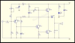
As you can see on virtually any tested and proven variation of JLH's design, most transistors are general purpose, low noise audio types, chosen to suit the voltages and currents used in the particular variation. The exception is Q3 (as shown in your attachment). This is the phase splitter and driver transistor for all four output devices. For best results, it must be one of the types suggested in the article or an equivalent with similar Ft and current ratings. This is not a simple duty and with the current-hungry output transistors shown on the schematic, I have my doubts about this beefed up version being as good as the basic JLH'69. YMMV but I wouldn't assume that your build will sound as good as the original unless you can better the nominated semis with what is available now. The choices in through-hole parts (if genuine) are very few.
You can also read old published magazine articles from Wireless World/E&WW and more threads on this topic. There several threads here that cover the driver transistor which you can search with Google etc. Some quite recent because this becomes a never-ending subjective argument when people attempt to claim that something "sounds better" but they can't offer any convincing evidence.
However, if you have read the TCAAS articles, you must already be aware of the matter and have seen what other transistor types are commonly suggested, thus avoiding the fake original TO39 steel case transistors that come with recent clone kits (you can rub the ink off with your fingers from many of them). Don't be surprised that there are few (if any) genuine substitutes for the original transitors and you may now need to adapt SOT 223 etc. SMD transistor types to get genuine parts or substitutes at reasonable prices.
Alternatively, if that is all too hard, experiment with what is offered in JLH'69 kits and see what burns or sounds good at full power, for little cost - At least you can't go too far wrong and you won't be simply following suggestions that may not be successful with your particular selection of components either.
You need to consider with today's Chinese and other unqualified sources, that you will probably be receiving "fake" or rather, unknown generic semis with fake markings. They may well be OK in some applications but how will they work in this difficult combination of duties? Note that 2 pairs of output transistors also doubles the standing bias current so the driver has to work twice as hard to supply the base current for that, as well as the signal drive current. As a result, the outcome may not be what you hoped for.
Thank you for the long reply ")
I have too little experience with amplifiers to be able to select transistors wisely..
Now I placed an order per my list above, and hope it will sound good.. However I only ordered one pair of outputs per channel to start with (lower voltage/current). I have some 'recycled' output transistors (however not TO3) that I might try too, but not sure what parameter are important for the JLH, seems people have different opinions on this. I already have a PNP JLH from Zerozone I mentioned earlier in the thread, and that one sounds (and measures) ok too.
Also ordered some parts to try the 'sublimed' mod to the white boards, but I will keep that in the other thread.
Last edited:
If you are referring to recycling plastic power transistors, remember that they are usually a lot faster than older, metal can types. As the TCAAS article says, they tend to show some instability in the JLH amplifier but good old 2N3055 semis and related slow transistors remain quite stable.
Fortunately, the 4MHz Ft rated MJL21193/4 types seem to be stable too. I think that's the better way to go, as having heard a JLH with an MJL21194 output stage, the sound quality in that build was definitely a step above the ancient steel case types. Be certain to have plenty of heatsink area and use mica/grease when mounting plastic power transistors for class A amplifiers, so you ensure the best possible heat transfer and avoid overheating the device.
Fortunately, the 4MHz Ft rated MJL21193/4 types seem to be stable too. I think that's the better way to go, as having heard a JLH with an MJL21194 output stage, the sound quality in that build was definitely a step above the ancient steel case types. Be certain to have plenty of heatsink area and use mica/grease when mounting plastic power transistors for class A amplifiers, so you ensure the best possible heat transfer and avoid overheating the device.
Last edited:
The Q3 transistor is the most important in the amplifier, it must have a small Cob and a large hFE. For output transistors I use fast 60MHz transistors and got the best sound with them, I only had an instability problem when I put in a Q3 transistor that had a Cob less than 2pF.
I have some instability on one of the white kit boards (not modified).
It's stable with no input signal, but when I put my finger on the input connector, it sometimes goes berserk, if I touch the heat sink or transistor case with my other hand at the same time, it is even worse.
The other one is ok when I do the same. The one with problems has a pair of outputs with higher gain. I did not measure the small signal transistors, since there is nothing to match.
I'm not shure if I paired the outputs in a good way. Example: if HFE was 1, 2, 3, 4 I put 1&3 on one channel, and 2 & 4 on the other. The board with the 2 & 4 is the one with oscillation.
Any suggestions what I could do to stabilize it?
Thank you!
I put two layers of isolation tape between PCB and heat sink at first assembly, but after I measured, one had connection to the heat sink anyway. When i loosened one screw a little bit, connection was gone, but oscillation was still there.
I took it apart again to add some isolation on the screws and transistor legs so they can't touch the heat sink, and replaced the 'pad' between transistor and heat sink. No connection after that This did not help oscillation. It behaves fine on DC level, adjustments work like they should.
I'm running only abt 1A Iq since I'm doing initial testing with a 1A bench supply, but that is also the same for both amps, and only one oscillates. Oscillation is violent, full swing. When it oscillates I can see current from the bench supply decrease. It stops oscillating when i remove my finger from the input pin, but it can take some time.
Maybe I should take another look on the heat sink/transistors/PCB again, could there be some small capacitance causing problems even if it's not shorted?
I removed all the output transistors, and double checked everything, swapped the pairs between the boards, and put it back together. Now both boards are equal, showing a slight oscillation when I touch the input with my finger. I have tested with signal from a sound card up to clipping with 5,6ohm load, and everything is ok.
I have done the 'finger test' with other amplifier board, and never seen a problem, but in this case maybe it was the test method that was the fault.. Anyway, now they behave the same even with the flawed test method
As a side note, I have played around with a FFT scope, watching for traces of switching from a HP laptop brick. I see the same profile on the output as on the 'input' (power to amp), even if it's lower. I guess PSRR is not so great on these amps? Most of it is out of the audio band, but there seem to be some kind of modulation down to the 5-7kHz area which I don't like.
Duffo adele, rallyfinnen is not replying to you, he is talking about his own problems with his build of this amp. Have a look back and you wil see what he is talking about. This thread is a bit like a crowded room, there are a number of conversations happening at the same time. Have patience and someone will talk to you about your problem.your answers do not match my question thank you
Hello
Could you tell me Why on a jlh2003 i find the voltage of the power on V out
Maybe you can get some indications here:
The Class-A Amplifier Site - DC Voltages
But I'm not sure what the difference is between 1996 and 2003..
I have got the white boards up and running. Ran them straight from the 19V HP laptop brick (rated 7A) yesterday, and they sounded fine in mid/treble, but 'lazy' in the bass. Today I added a 15mF capacitor on the supply and first impression is that it improved the bass a bit, but I would not call it punchy and tight.
Set Iq to 1,4A, which is about what my temporary setup will handle safely. There seems to be bad thermal contact between transistors and the supplied alu-piece using the supplied pads, there is a big diff in temp between the two.
I did some quick distortion measurements to verify that they are ok (abt 1W 8ohm), and it looks like similar distortion levels and distortion profile as the JLH pnp from zerozone I have from before, maybe a little more distortion on these. However distortion levels differs between the two boards (almost 10db on 2nd harmonic with 1kHz 1W). I would guess this is because the hfe of the output transistors varied quite a bit (and I guess on the other transistors too), so open loop gain is quite diffrent between them?
I only measured the hfe with a multimeter at assembly, and I think lowest showed 37, and highest 117. I know it's not a good way to measure them, but I think it gives some kind of indication of the mismatch.
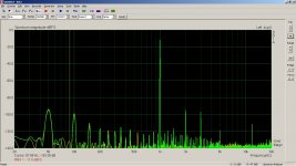
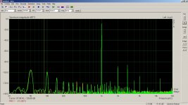
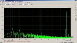
Some distortion measurements with MJ15003G
So, I decided to try the white Chinese board with MJ15003G output transistors, since they have been reported to work well with this amp.
I'm a little bit exited about the measurements, so I'm posting some screenshots here. Filenames explain the conditions. Supply to the amps is a 19,5V laptop brick. There is some 50hz and more picked up by the setup, so concentrate on the peaks from the harmonics, and look away from some of the odd peaks/grass elsewhere. All graphs have both channels, with one as overlay. No averaging (I was in a hurry), so the grass would be smoother with averaging.
First, after installing them, I saw that both amps were performing equally, and that was not the case with the transistors that came with the boards. I had the Iq set to abt 1,3A, and it all looked as I expected.
I decided to play around a little with it with FFT running, and that's what got me a bit excited. With a relatively cold amp, I slowly turned it up, and first the distortion decreased a little bit, but suddenly there was a instant dive in the distortion around 1,7A. Mainly the second harmonic that jumped down more than 10dB. If I turned up the current more, it jumped back up again. It was even more significant on the IMD. Here I was almost 20dB down on the sweet spot, compared to 1,3A.
So, I tuned the current to give the lowest IMD and left the amp on for some time. After heating up, the current was up to abt 1,9A, but it seems the 'sweet spot' was still correct, if I adjusted the current either way, distortion went up.
First I was not able to get the IMD to the same level on both amps, so I decided to play around a little with the 'offset' adjustment. I had only adjusted this roughly by observing clipping on the scope. With some adjustment on the offset adjustment, I was able to get the IMD to the same level on both boards.
I'm clueless to how/why this works, but I was amazed to see the result. Must be some 'sweet spot' where the amp is more linear. Maybe more a factor of the potentiometer settings than the actual current?
One might think this is only at high output, with more current available to feed to the load, but the distortion decreases over the whole range.
One observation is that the optimal current is possibly a little bit different depending on frequency, but I'm not sure about this. It seemed I had to adjust the screw slightly to get minimal 2nd order distortion when I had 100Hz, 1KHz and 5KHz sine input.
Will give it a listen now and wait what my ears tell me.
Before I had a headache after listening to it for a couple of hours, but I'm listening on new speakers, so that's a factor too. However, no headache with another amp and the same speakers.
I'm a little bit nervous about running such a high current, but at least the transistors are from a trusted source, so at least they should not be over sensitive.
Attachments
On the white Chinese board you have a 220 ohms behind the led . It is quarter watt but by Chinese magic it is dissipating half. After you have adjusted the bias by the series adjust , measure the total resistance it becomes with the 220 ohm . You can vary now the tap point all keeping the sum constant , to adjust the second harmonic .
Referring to the attached schematic for the white board, you mean R8 and KT2?
So with a desired Iq the total resistance of these could be replaced with a potentiometer with this new resistance (let's say it exists in theory), and the wiper on the potentiometer connected to C4?
I'm I understanding you correctly?
So, the sweet spot I'm seeing is not due to the Iq (as I suspected) but due to the balance between the output transistors, cancelling the 2nd harmonic?
What I found most interesting with the measurements was the impact on the IMD, it was really a significant change.
2nd harmonic by itself I'm not so worried about, but in my experience, amps with high IMD (and a lot of high order harmonics) has always sounded harsh and flat (not much depth) to my ears. The impression is the same now when I listen to the white boards after the mod, the sound is significantly improved in mid and highs. Still the bass is a little bit muddy and 'soft', but not too bad.
I think the next step will be to try your sublimed version. I have the components already, so it's just a matter of getting it done. I think there will be some questions for you in that thread when I get started (have one in mind already about Iq adjustment)
Attachments
- Home
- Amplifiers
- Solid State
- JLH 10 Watt class A amplifier