I think DN2540 is obsolete now. A depletion type if I am right? More like a jfet or vacuum tube. Again a bipolar CCS would be interesting and what best sets standing current. BC327-40 could work. An emitter resistor almost ensures linearity and is the current setting. Most MOS FET and all bipolar are enhancement (?) devices. The CCS for them look different. Bipolar types need about 0.55 to 0.7 volts to to switch on. This means a calculated design will be very close to actual result. Other devices may spread 2 to 4 volts.
The DN2540 is still in production, in three different cases.
dn2540 Microchip MOSFET | Mouser Croatia
DN2540 is depletion type and in my case it needs Vgs of -0.8V for 30mA. This CCS I think to improving with a better mosfet with lower Vds and maybe with a cascade with FET at a lower position although DN is doing its job well.
In the past few years I've been playing a lot with CCS and I like the sound of DN2540a at higher currents.For less current I prefer FETs. The BJT CCS in the simulator has a slightly smaller distortion than the DN2540,so I'll try it one day though I know it will not be better than the DN2540.
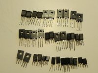
This is a collection of transistors I've tried for Tr3. There is a difference in the sound whether the scheme is with botstrap or with the CSS for Tr3. 2SC3421 I deliberately left the end because it was listed as the best replacement for 2N1711. And now I can say it's not worthy of that title.
My favorites are 2SC1941, 2SC3116, 2SD571, 2SD438, KSC2682, KSC3505 and 2SC3423. The 2SC3421 is missing the stage width, somehow it is muddy.
My favorites are 2SC1941, 2SC3116, 2SD571, 2SD438, KSC2682, KSC3505 and 2SC3423. The 2SC3421 is missing the stage width, somehow it is muddy.
Attachments

Hi Martyh, Re: JLH headphone amp' are you aware that he did create a dedicated headphone amp' based on the '69 power amp?
Just might save you "reinventing the wheel".
Paul Kimble has assembled a lot of his audio circuitry at the following site,
(A Paul Kemble web page - John Linsley Hood preamp designs.)
The HFN-RR amp is about a quarter of the way down the page.....its split rail too.
Its got a 'tone control' attached to the front but that's not an issue....
cheers, Jonathan
Hi Folks
I was cleaning up my list of favourites and came (again) accross Stan Curtis' site. Stan appears to have a straight forward, no nonsense attitude towards amplifiers and Hi-Fi in general.
Of particular interest was his musing on various topics in various articles that can be found here:
Stan Curtis, Engineer, articles from HiFi Critic magazine
More to the point of this thread, a sort of inclination/rationale for the use of Class A amplfiers and of simple design that can be found in Stan's Safari part 3.
I have always had this notion (with nothing to substantiate it) that the minium number of amplifying elements in an audio chain is a way to reproducing a good sound - "Far too many transistors Mr Mozart" (with applogies to W. A.)
Worth a read
Happy listening
Mike
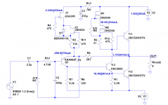
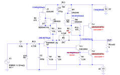
Here is a new version of JLH with CCS, the first CCS formed by a pair of cascoded FETs, and the second with cascoded depletion MOSFETs. The sound is really great, so far the best improvement.
Attachments
Last edited:
Member
Joined 2009
Paid Member
Original JLH documentation that is becoming hard to find online. JLH Library
Last edited:

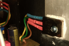
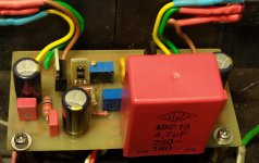
This is a small circuit I built to say the car is charging the battery. If other LED or transistor used it might need a small adjustment, LED is cheapest Kingbright type. I use the cigar lighter socket. When parked the LED is mostly off and at a typical 14.2 VDC bright. The 10K sets how bright. My car is old so it's a wise precaution. It is so dull when parked it shouldn't drain the battery. When the battery has settled the voltage drops below the LED voltage. It gives slight output when just charged with engine off.
A thought came to me. If the 27K is adjusted a pair could be used to show JLH centre voltage. If set up carefully the eye will see any change. Quad used this idea for tuning a FM tuner. Hope you like the circuit. It's slightly less good than a comparator and better than a zener. I didn't fit the 1N4007 myself. Not a bad idea to have it, it's reverse biased. One would be fitted to the + rail and one to the bottom and the two spare ends to the centre speaker output.
A few days ago I changed the outputs in my JLH amplifier. I put 2SC3284 Y (hFE 170-180) instead of 2SC5242 O. The current through Tr3 has dropped significantly to ~ 10mA. In my measurements Sanken has almost double hFE according to 2SC5242 O. There is also a big difference in fT, 60MHz vs. 30MHz, Cob is the same.
After installing new CCSs https://www.diyaudio.com/forums/solid-state/3075-jlh-10-watt-class-amplifier-553.html#post5686739, oscillations occurred when using 2SC1941 K with Cob below 3pF for Tr3. The problem was solved by adding mica 4.7pF in parallel with R9. The same capacitor stayed with 2SC3284 and now works without problems with 2SC1941. For Tr3 I have more favorites to try.https://www.diyaudio.com/forums/solid-state/3075-jlh-10-watt-class-amplifier-553.html#post5678173 For now I have tried KSC2682 and 2SC1941 and can not decide which one is better. I'm waiting for an independent hi-fi listener.
The amplifier sounds again better, the more details come to light and the lower part of the bandwidth is also gained on the dynamics.
Attachments
A few days ago I changed the outputs in my JLH amplifier. I put 2SC3284 Y (hFE 170-180) instead of 2SC5242 O. The current through Tr3 has dropped significantly to ~ 10mA. In my measurements Sanken has almost double hFE according to 2SC5242 O. There is also a big difference in fT, 60MHz vs. 30MHz, Cob is the same.
After installing new CCSs https://www.diyaudio.com/forums/solid-state/3075-jlh-10-watt-class-amplifier-553.html#post5686739, oscillations occurred when using 2SC1941 K with Cob below 3pF for Tr3. The problem was solved by adding mica 4.7pF in parallel with R9. The same capacitor stayed with 2SC3284 and now works without problems with 2SC1941. For Tr3 I have more favorites to try.https://www.diyaudio.com/forums/solid-state/3075-jlh-10-watt-class-amplifier-553.html#post5678173 For now I have tried KSC2682 and 2SC1941 and can not decide which one is better. I'm waiting for an independent hi-fi listener.
The amplifier sounds again better, the more details come to light and the lower part of the bandwidth is also gained on the dynamics.
There are two things you can do without getting an independent hi-fi listener.
First one can get used to the change over a period since it takes some time to adjust to differences or in my case I can ask my wife to listen. That can be a quick reality check.
There was an engineer named Eckersley who famously said about bandwidth "the wider you open the door the more the muck flies in". In this case it is the back door with a 4.7pF capacitor as the foot keeping this open.
Hi Grunf,
how do you compare your comparisons? ... you have news?
Thank you and greetings.
Mleod
The decision fell to 2SC1941 which has a more natural sound, 2SC2682 is a little tough, but both are great, beautiful space and details.
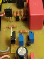
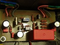
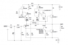
I made another change today, instead of the bottom DN2540 in TO92 I inserted two FETs 2SK3557-7 in parallel. I also changed the input polypropylene from 2.2 to 4.7uF.
The sound was again improved. The same combination of CCS with MOSFET and double FET I have already used for tubes with excellent results so I'm not surprised by the result at JLH69.
At the moment this is one of the better (and perhaps the best) amplifier I've listened to.
Attachments
Hi Grunf,
Thank you for the information you have given and I hope you will still want to provide if there were further developments. I took the liberty of asking why in the past I mounted a pair of JLH 2005 with the same power supply voltage and with the CCAs in BJT, as per the original scheme and since this development of yours represents a more modern implementation, it intrigues me where it will ever be to arrive in terms of acoustic performance.
Thanking you again for your kindness and competent availability, I offer my greetings.
Mleod
Hi All,
I am finishing off and testing my high-power JLH amp, based of Geoff Moss' variation, ( + and - rails with no output cap) and came accross a small anomoly.
When building the amp, I built a test set for measuring voltage rails and the current in the + and - supplies. To measure current, I put a 0.1 resistor in both rails and used a floating 5 digit digital voltmeter to measure the voltage accross the 0.1 ohm, this giving me a reading of current/10.
The set up is a seperate power supply that houses the mains transformer, rectifier and initial smoothing of 30,000uF. This then links via a short unbilical cable to the amplifier chassis that has a further 45,000uF and a cap multiplier that then feeds the amp board. The design is a complete dual mono-block, including the power supplies.
So having tested the amp and set it up, I measured the distorting before and after the test set was in circuit. To my surprise, the distortion increased with the test box out of circuit. The only reason I could see for this was the 0.1 ohm Caddock resistor in each rail.
So I modified the power supply to have a resistor in both of the rails and the distortion came back down to the value that I originally had with the test set in place.
So what is going on? I remember a comment that one constructor had when building their JLH (I forget which version) where they originally had a 0.33 ohm resistor in the +rail to measure current. When they bypassed it they felt that the sound was worse - in what way they did not say.
Geoff's response was that he could not see a reason for this in theory or simulation.
The unbilical cable and connectors are all good - no dodgy contacts or joints - high current naval connectors are used throughout with 15 amp cables.
The only point I can highlight is that the initail smoothing, the 0.1ohm Caddock and the secondary smoothing caps form a C-R-C circuit, which will lower ripple and charging sawtooth, but the Cap multipler does this very succesfully anyway and the ripple to the amp is a few millivolts.
Otherwise the amp performs great, it delivers just over 80 watts into an 8 Ohm load with distortion at full power being 0.060%.
Any thoughts as to what is going on?
Kind regards
Mike
Last edited:
For what its worth I can throw in a possible explanation but "from left field". Prof Edward Cherry, of NDFLoops fame, identified a new distortion mechanism 30 odd yrs ago. But this was Class B amps. Now I can't put my fingers on the paper at the moment but it was quite low level, numerically. He resolved it by including small inductors in the PSU lines and specifying a very particular routing of the copper traces on the circuit board near were the PS meets the electronics/output stage. This was included in a 60Watt DIY amp published in ETI. But the thing that's suck in my mind is the fact that the inductors had a small specified resistance, about 0.15 Ohms from memory. It was taken seriously enough for the JAES to give him a couple of pages in one edition probably in the "Engineering Briefs" section.
I'll try and refine these ramblings with some references.
Cheers Jonathan
I'll try and refine these ramblings with some references.
Cheers Jonathan
Last edited:
Is the secondary winding of the transformer centre-tapped by any chance? A transformer with 2 x 18V windings would be just right for a "dual mono" version, where separate power supplies for each channel are required.......I have a problem because id like to use a 100VA transformer with 36volt output. What are the mod I must change in order to use this transformer or should i just buy new transformer?
- Home
- Amplifiers
- Solid State
- JLH 10 Watt class A amplifier