https://docs-emea.rs-online.com/webdocs/12cf/0900766b812cfc33.pdf
Cob 8pF at 30V shown on graph. 10pF at 10V. Y gain range 160-320. Ft 100 MHz typical. High current if required and 0.9W in TO92L centre collector.
Cob 8pF at 30V shown on graph. 10pF at 10V. Y gain range 160-320. Ft 100 MHz typical. High current if required and 0.9W in TO92L centre collector.
As for going in circles, I would say only recently has some of the deep thuth's of the design come alive. What is the point of having a version of JLH if how to question it's set up is not put forward. Setting the bias if a little thinking is done can be by ear. How often in DIY Audio would we say that?
Thimios. What spectrum analyser are you using?
Quad 303 + ESL 57. The point I was making there is take the 303 which is the dull side of neutral and then roll the speakers off using it's transformer. Quad obviously felt people prefer 20 kHz maximum. Ironicallly Celestion SL6 has a very similar sound balance and was often thought to be the best small speaker of it's day. They sound very good with Nain NAP 250 which I doubt ever happened in real life. The faults of both seem to vanish. ESL 57 and Naim Nait 2 is unbeatable. The 303 less good if trying to get a bit more HF. I would suggest 57's and Nait better than nearly anything shown at hi fi shows. Naim used 57's as a reference. I would guess JLH + 57's to be magical. Magnepan SMGa a poormans version. The Magnepan if set up to give a one listener window might outperform 57's. Both they and 57's go louder than the specs suggest due to how they work.
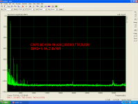
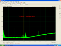
A p.c based fft analyzer has been used.
Sound card is an EsiJulia.
Software is Arta.
I have two version JLH.
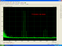
One using bc 560c, bd139-16,ksc3503d,TTC5200 (prasi's red pcb.
One using the same but 2N3055H.
Second, using"tsca970,bd139-16,ksc3503d,TTC5200(prasi's long black pcb).
The last one same pcb but with ksa992, bd139-16,ksc3503d,MJE15024.
Sound card is an EsiJulia.
Software is Arta.
I have two version JLH.
One using bc 560c, bd139-16,ksc3503d,TTC5200 (prasi's red pcb.
One using the same but 2N3055H.
Second, using"tsca970,bd139-16,ksc3503d,TTC5200(prasi's long black pcb).
The last one same pcb but with ksa992, bd139-16,ksc3503d,MJE15024.
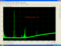
LOOKING FOR OPTIMAL SETTING
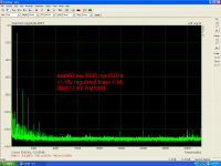
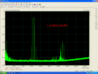
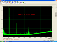
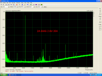
I will post some picture when trying finding the optimal bias setting.
bias=1.1A.
POWER SUPPLY IS REGULATED+/-18V
I will post some picture when trying finding the optimal bias setting.
bias=1.1A.
POWER SUPPLY IS REGULATED+/-18V
Attachments
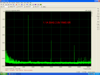
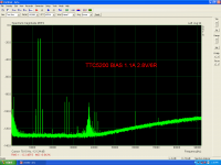
LOOKING FOR OPTIMAL SETTING
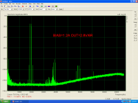
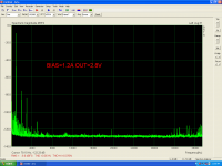
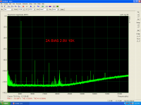
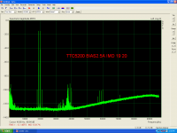
Now bias=2A.
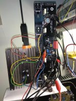
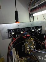
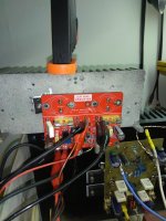
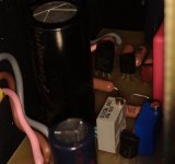
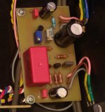
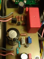
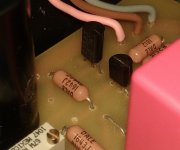
In all cases this is the board under test.
Now bias=2A.
In all cases this is the board under test.
Attachments
Last edited:
A p.c based fft analyzer has been used.
Sound card is an EsiJulia.
Software is Arta.
I have two version JLH.
One using bc 560c, bd139-16,ksc3503d,TTC5200 (prasi's red pcb.
One using the same but 2N3055H.
Second, using"tsca970,bd139-16,ksc3503d,TTC5200(prasi's long black pcb).
The last one same pcb but with ksa992, bd139-16,ksc3503d,MJE15024.
Thank you.
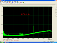
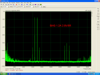
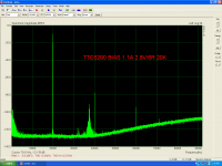
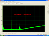
LOOKING FOR OPTIMAL SETTING
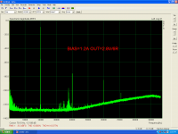
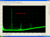
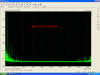
Now using a970,bd139-16,ksc3503d TTC5200.
Now using a970,bd139-16,ksc3503d TTC5200.
Attachments
Last edited:


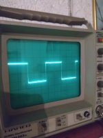
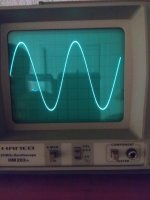
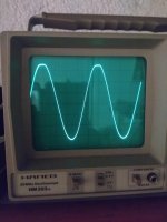
Sensivity and power measurment
Inp=919mV
Out=11.5v RMS before clip
Rload=6R
Power=22w RMS.
Power supply=+/-18v
Bias=2.5A
Tested at this board.
And some early scope pictures
Inp=919mV
Out=11.5v RMS before clip
Rload=6R
Power=22w RMS.
Power supply=+/-18v
Bias=2.5A
Tested at this board.
And some early scope pictures
Attachments
Last edited:
JLH69 I made ten days ago with the BD139-16 PHI for Q3 and sounded great to me. Then I tried Japanese transistors.
I have 2SD468, 2SC2383 and TTC004, I've tried them in the last three days. Unfortunately, 2SC2383 that I have is version O (hfe 170). 2SD468 has hfe 300 and TTC004 hfe 220.The amplifier was stable with all three transistors.
2SD468 is my favorite, 2SC2383 is also great, while the TTC004 is disappointed (at least for now).
The TTC004 does not have a lot of work hours so it will get another chance. This week I will try to do some measurements with 2SC2383 in the amplifier.
Attachments
I did try BC337-40. It seemed to cope. I had to fit 33 pF to get complete stability. I think if I had tried 12 pF it might have worked as the instability was only just detectable. I am in the process of moving house so will restart building a JLH when my new workshop built. For an 8 ohm version it seemed happy. BC327/337 are easier to get and seem genuinely able to to do more other common choices. I would imagine a genuine 2SD756 would be very good. BC327/337 are very low noise, high gain and good current. Distortion using BC337-40 seemed to better common examples. I think below 0.05% 5 watts is possible even at 10 kHz.
I tried BC337-40 in LTspice, and at 14W there are distortions about 0.04% of 1kHz to 20kHz. Input transistor is 2SA992 and output 2SC5200, bias 1.75A, +/- 21V.
I only feared endurance as it was only 625mW
Evening gents, I have dragged this out of the cupboard to give me something to do indoors. The boards are built, I am assembling the case. However I forgot about the need to multiply AC supply voltage by 1.4 so my 35V ac transformer is giving me 48V DC off the rectifier. Is this going to be OK or is it a Star Trek "She cannae take it Cap'n" moment? If it's too much I can put the centre tap on the rectifier and get 24V DC at the rectifier, it will work but be low powered.
mj15016
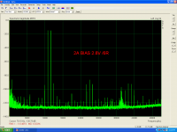
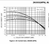
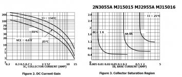
thimios , what is the difference of 2n3055H , the ON datasheet gives the same . If you look the Hfe curves , the mj15015G=2n3055AG is continuously decreasing where the 2n3055 stabilizes . This means at 1.2A bias the mj15015 has less odd harmonics . Have you ever tried it ?
thimios , what is the difference of 2n3055H , the ON datasheet gives the same . If you look the Hfe curves , the mj15015G=2n3055AG is continuously decreasing where the 2n3055 stabilizes . This means at 1.2A bias the mj15015 has less odd harmonics . Have you ever tried it ?
Attachments
Inp=919mV
Out=11.5v RMS before clip
Rload=6R
Power=22w RMS.
Power supply=+/-18v
Bias=2.5A
Tested at this board.
And some early scope pictures
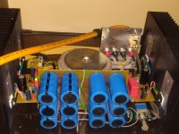
I would say as good as it can be... Nice vintage logo on the PCB, suits well😊..
Congrats on successful build and thanks for sharIng here...
Regards
Prasi
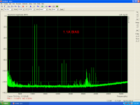
Very interesting. It's not 100 % certain 2.5 amps is better. The 1.1 A version has it's harmonics in a very nice order. OK the 2.5 amp version is better in an absolute sense, both better the JLH intended < 0.1% THD. The KEF LS50 speaker has 0.8% THD and the Quad ESL 63 0.1%.if not listening at maximum with full bass. Most speakers exceed 2%. Some say harmonics > 10 kHz don't count. Hard to say. When class AB I prefer not to see them.
Has anyone increased the sensetivity to run directly from CD? At 2.5 amps bias it should be very OK. I think the spectrum should look good and maybe a faster transistor used without Cdom fitted.
If hiss a problem my long tail pair input could be used. If so input bootstrap to use a lower input resistor. As the LTP has unitity voltage to the basses and in phase it can be coupled to the input via a capacitor and series resistor. Whilst it looks dreadful the distortion will be very low. I would guess 3K3 + 3K3 could be used. Take that to be about 1K and set the capacitance to be < 5Hz . C = 1/ 6.284 x 5 x 1000 =>33 uF. Depending on +/- PSU a non polar might be best. If understanding the needs the original JLH could do this. When class A it is a very reasonable thing to do as no crossover spikes returned to the input. The link I give would could suit the JLH. The point with bootstraps I have found is limit them to about 93% positive feedback. Even 50% is useful. 97% can cause trouble. A series resistor helps. 220R typical.
Transistor Bootstrapping Circuit Using BJT
- Home
- Amplifiers
- Solid State
- JLH 10 Watt class A amplifier